CCNA Practice tests. CCNA exam is now 200-301. Here are free practice tests questions and answers. try this 25 questions with answers. for CCNA exam practice. OSI/TCP Model Questions Q1.…
IP Routing in the LAN

VLAN Routing with Router 802.1Q Trunks
Almost all enterprise networks use VLANs. To route IP packets in and out of those VLANs, some devices (either routers or Layer 3 switches) need to have an IP address in each subnet and have a connected route to each of those subnets. Then the IP addresses on those routers or Layer 3 switches can serve as the default gateways in those subnets.
[ufwp search=”Cisco CCNA Routing & Switching 1: LAN Switching Technologies” items=”1″ template=”list”]
This chapter breaks down the LAN routing options into four categories:
- Use a router, with one router LAN interface and cable connected to the switch for each and every VLAN (typically not used)
- Use a router, with a VLAN trunk connecting to a LAN switch (known as router-on-a-stick, or ROAS)
- Use a Layer 3 switch with switched virtual interfaces (SVI)
- Use a Layer 3 switch with routed interfaces (which may or may not be Layer 3 EtherChannels)
Of the items in the list, the first option works, but to be practical, it requires far too many interfaces. It is mentioned here only to make the list complete.
As for the other three options, this chapter discusses each in turn as the main focus of one of the three major sections in this chapter. Each feature is used in real networks today, with the choice to use one or the other driven by the design and needs for a particular part of the network. Figure 17-1 shows cases in which these options could be used.
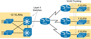
Figure 17-1 shows two switches, labeled A and B, which could act as Layer 3 switches—both with SVIs and routed interfaces. The figure shows a central site campus LAN on the left, with 12 VLANs. Switches A and B act as Layer 3 switches, combining the functions of a router and a switch, routing between all 12 subnets/VLANs, as well as routing to/from the Core router. Those Layer 3 switches could use SVIs, routed interfaces, or both.
Figure 17-1 also shows a classic case for using a router with a VLAN trunk. Sites like the remote sites on the right side of the figure may have a WAN-connected router and a LAN switch. These sites might use ROAS to take advantage of the router’s ability to route over an 802.1Q trunk.
Note that Figure 17-1 just shows an example. The engineer could use Layer 3 switching at each site or routers with VLAN trunking at each site.
Configuring ROAS
This next topic discusses how routers route packets to subnets associated with VLANs connected to a router 802.1Q trunk. That long description can be a bit of a chore to repeat each time someone wants to discuss this feature, so over time, the networking world has instead settled on a shorter and more interesting name for this feature: router-on-a-stick (ROAS).
ROAS uses router VLAN trunking configuration to give the router a logical router interface connected to each VLAN. Because the router then has an interface connected to each VLAN, the router can also be configured with an IP address in the subnet that exists on each VLAN.
Routers use subinterfaces as the means to have an interface connected to a VLAN. The router needs to have an IP address/mask associated with each VLAN on the trunk. However, the router has only one physical interface for the link connected to the trunk. Cisco solves this problem by creating multiple virtual router interfaces, one associated with each VLAN on that trunk (at least for each VLAN that you want the trunk to support). Cisco calls these virtual interfaces subinterfaces. The configuration can then include an ip address command for each subinterface.
Figure 17-2 shows the concept with Router B1, one of the branch routers from Figure 17-1. Because this router needs to route between only two VLANs, the figure also shows two subinterfaces, named G0/0.10 and G0/0.20, which create a new place in the configuration where the per-VLAN configuration settings can be made. The router treats frames tagged with VLAN 10 as if they came in or out of G0/0.10 and frames tagged with VLAN 20 as if they came in or out G0/0.20.
)
In addition, note that most Cisco routers do not attempt to negotiate trunking, so both the router and switch need to manually configure trunking. This chapter discusses the router side of that trunking configuration; the matching switch interface would need to be configured with the switchport mode trunk command.
Example 17-1 shows a full example of the 802.1Q trunking configuration required on Router B1 in Figure 17-2. More generally, these steps detail how to configure 802.1Q trunking on a router:

- Step 1. Use the interface type number.subint command in global configuration mode to create a unique subinterface for each VLAN that needs to be routed.
- Step 2. Use the encapsulation dot1q vlan_id command in subinterface configuration mode to enable 802.1Q and associate one specific VLAN with the subinterface.
- Step 3. Use the ip address address mask command in subinterface configuration mode to configure IP settings (address and mask).
Example 17-1 Router Configuration for the 802.1Q Encapsulation Shown in Figure 17-2
B1# show running-config
! Only pertinent lines shown
interface gigabitethernet 0/0
! No IP address up here! No encapsulation up here!
!
interface gigabitethernet 0/0.10
 encapsulation dot1q 10
 ip address 10.1.10.1 255.255.255.0
!
interface gigabitethernet 0/0.20
 encapsulation dot1q 20
 ip address 10.1.20.1 255.255.255.0
First, look at the subinterface numbers. The subinterface number begins with the period, like .10 and .20 in this case. These numbers can be any number from 1 up through a very large number (over 4 billion). The number just needs to be unique among all subinterfaces associated with this one physical interface. In fact, the subinterface number does not even have to match the associated VLAN ID. (The encapsulation command, and not the subinterface number, defines the VLAN ID associated with the subinterface.)
NOTE
Although not required, most sites do choose to make the subinterface number match the VLAN ID, as shown in Example 17-1, just to avoid confusion.
Each subinterface configuration lists two subcommands. One command (encapsulation) enables trunking and defines the VLAN whose frames are considered to be coming in and out of the subinterface. The ip address command works the same way it does on any other interface. Note that if the physical Ethernet interface reaches an up/up state, the subinterface should as well, which would then let the router add the connected routes shown at the bottom of the example.
Now that the router has a working interface, with IPv4 addresses configured, the router can route IPv4 packets on these subinterfaces. That is, the router treats these subinterfaces like any physical interface in terms of adding connected routes, matching those routes, and forwarding packets to/from those connected subnets.
The configuration and use of the native VLAN on the trunk require a little extra thought. The native VLAN can be configured on a subinterface, or on the physical interface, or ignored as in Example 17-1. Each 802.1Q trunk has one native VLAN, and if the router needs to route packets for a subnet that exists in the native VLAN, then the router needs some configuration to support that subnet. The two options to define a router interface for the native VLAN are

- Configure the ip address command on the physical interface, but without an encapsulation command; the router considers this physical interface to be using the native VLAN.
- Configure the ip address command on a subinterface and use the encapsulation dot1q vlan-id native subcommand to tell the router both the VLAN ID and the fact that it is the native VLAN.
Example 17-2 shows both native VLAN configuration options with a small change to the same configuration in Example 17-1. In this case, VLAN 10 becomes the native VLAN. The top part of the example shows the option to configure the router physical interface to use native VLAN 10. The second half of the example shows how to configure that same native VLAN on a subinterface. In both cases, the switch configuration also needs to be changed to make VLAN 10 the native VLAN.
[ufwp search=”CCNA R & S 200-125 v3.0 – 1.0 LAN Switching Labs” items=”1″ template=”list”]
Example 17-2 Router Configuration Using Native VLAN 10 on Router B1
! First option: put the native VLAN IP address on the physical interface
interface gigabitethernet 0/0
 ip address 10.1.10.1 255.255.255.0
!
interface gigabitethernet 0/0.20
 encapsulation dot1q 20
 ip address 10.1.20.1 255.255.255.0
! Second option: like Example 17-1, but add the native keyword
interface gigabitethernet 0/0.10
 encapsulation dot1q 10 native
 ip address 10.1.10.1 255.255.255.0
!
interface gigabitethernet 0/0.20
 encapsulation dot1q 20
 ip address 10.1.20.1 255.255.255.0
Verifying ROAS
Beyond using the show running-config command, ROAS configuration on a router can be best verified with two commands: show ip route [connected] and show vlans. As with any router interface, as long as the interface is in an up/up state and has an IPv4 address configured, IOS will put a connected (and local) route in the IPv4 routing table. So, a first and obvious check would be to see if all the expected connected routes exist. Example 17-3 lists the connected routes per the configuration shown in Example 17-1.
Example 17-3 Connected Routes Based on Example 17-1 Configuration
B1# show ip route connected
Codes: L - local, C - connected, S - static, R - RIP, M - mobile, B - BGP
! Legend omitted for brevity

      10.0.0.0/8 is variably subnetted, 4 subnets, 2 masks
C        10.1.10.0/24 is directly connected, GigabitEthernet0/0.10
L        10.1.10.1/32 is directly connected, GigabitEthernet0/0.10
C        10.1.20.0/24 is directly connected, GigabitEthernet0/0.20
L        10.1.20.1/32 is directly connected, GigabitEthernet0/0.20
As for interface and subinterface state, note that the ROAS subinterface state does depend to some degree on the physical interface state. In particular, the subinterface state cannot be better than the state of the matching physical interface. For instance, on Router B1 in the examples so far, physical interface G0/0 is in an up/up state, and the subinterfaces are in an up/up state. But if you unplugged the cable from that port, the physical port would fail to a down/down state, and the subinterfaces would also fail to a down/down state. Example 17-4 shows another example, with the physical interface being shut down, with the subinterfaces then automatically changed to an administratively down state as a result.
Example 17-4 Subinterface State Tied to Physical Interface State
B1# configure terminal
Enter configuration commands, one per line. End with CNTL/Z.
B1(config)# interface g0/0
B1(config-if)# shutdown
B1(config-if)# ^Z
B1# show ip interface brief | include 0/0
GigabitEthernet0/0         unassigned      YES manual administratively down down
GigabitEthernet0/0.10      10.1.10.1       YES manual administratively down down
GigabitEthernet0/0.20      10.1.20.1       YES manual administratively down down
Additionally, the subinterface state can also be enabled and disabled independently from the physical interface, using the no shutdown and shutdown commands in subinterface configuration mode.
Another useful ROAS verification command, show vlans, spells out which router trunk interfaces use which VLANs, which VLAN is the native VLAN, plus some packet statistics. The fact that the packet counters are increasing can be useful when verifying whether traffic is happening or not. Example 17-5 shows a sample, based on the Router B1 configuration in Example 17-2 (bottom half), in which native VLAN 10 is configured on subinterface G0/0.10. Note that the output identifies VLAN 1 associated with the physical interface, VLAN 10 as the native VLAN associated with G0/0.10, and VLAN 20 associated with G0/0.20. It also lists the IP addresses assigned to each interface/subinterface
Example 17-5 Sample show VLANs Command to Match Sample Router Trunking Configuration
R1# show vlans
Virtual LAN ID: 1 (IEEE 802.1Q Encapsulation)

   vLAN Trunk Interface: GigabitEthernet0/0

   Protocols Configured:  Address:        Received:    Transmitted:
        Other                                    0              83

   69 packets, 20914 bytes input
   147 packets, 11841 bytes output

Virtual LAN ID:   10 (IEEE 802.1Q Encapsulation)

    vLAN Trunk Interface:   GigabitEthernet0/0.10

 This is configured as native Vlan for the following interface(s) :
GigabitEthernet0/0      Native-vlan Tx-type: Untagged

      Protocols Configured:   Address:     Received:    Transmitted:
              IP              10.1.10.1           2               3
           Other                                  0               1

   3 packets, 722 bytes input
   4 packets, 264 bytes output

Virtual LAN ID:   20 (IEEE 802.1Q Encapsulation)

    vLAN Trunk Interface:   GigabitEthernet0/0.20

    Protocols Configured:  Address:        Received:  Transmitted:
            IP             10.1.20.1              0           134
         Other                                    0             1

    0 packets, 0 bytes input
    135 packets, 10498 bytes output

[ufwp search="    Connecting to the Internet: A Practical Guide about LAN-Internet Connectivity" items="1" template="list"]
Troubleshooting ROAS
The biggest challenge when troubleshooting ROAS has to do with the fact that if you misconfigure only the router or misconfigure only the switch, the other device on the trunk has no way to know that the other side is misconfigured. That is, if you check the show ip route and show vlans commands on a router, and the output looks like it matches the intended configuration, and the connected routes for the correct subinterfaces show up, routing may still fail because of problems on the attached switch. So, troubleshooting ROAS often begins with checking the configuration on both the router and switch because there is no status output on either device that tells you where the problem might be.
First, to check ROAS on the router, you need to start with the intended configuration and ask questions about the configuration:
- Is each non-native VLAN configured on the router with an encapsulation dot1q VLAN-id command on a subinterface?
- Do those same VLANs exist on the trunk on the neighboring switch (show interfaces trunk), and are they in the allowed list, not VTP pruned, and not STP blocked?
- Does each router ROAS subinterface have an IP address/mask configured per the planned configuration?
- If using the native VLAN, is it configured correctly on the router either on a subinterface (with an encapsulation dot1q VLAN-id native command) or implied on the physical interface?
- Is the same native VLAN configured on the neighboring switch’s trunk in comparison to the native VLAN configured on the router?
- Are the router physical or ROAS subinterfaces configured with a shutdown command?
For some of these steps, you need to be ready to investigate possible VLAN trunking issues on the LAN switch. The reason is that on many Cisco routers, router interfaces do not negotiate trunking. As a result, ROAS relies on static trunk configuration on both the router and switch. If the switch has any problems with VLANs or the VLAN trunking configuration on its side of the trunk, the router has no way to realize that the problem exists.
For example, imagine you configured ROAS on a router just like in Example 17-1 or Example 17-2. However, the switch on the other end of the link had no matching configuration. For instance, maybe the switch did not even define VLANs 10 and 20. Maybe the switch did not configure trunking on the port connected to the router. Even with blatant misconfiguration or missing configuration on the switch, the router still shows up/up ROAS interfaces and subinterfaces, IP routes in the output of show ip route, and meaningful configuration information in the output of the show vlans command.
This chapter is from the book CCNA 200-301 Official Cert Guide, Volume 1
[ufwp search=”lan” items=”6″ template=”grid” grid=”3″]