CCNP Data Center 300-620 [DCACI]Data Center ACI Implementation

300-620 DCACI Cisco Certified Specialist, Data Center ACI Implementation Exam
Implementing the Cisco Application Centric Infrastructure v1.0 (DCACI 300-620) exam is a 90-minute exam that is associated with the CCNP Data Center Certification and Cisco Certified Specialist – Data Center ACI Implementation certifications.

The exam tests a candidate for the knowledge of Cisco switches in ACI mode including configuration, implementation, and management.
This exam tests your knowledge of Cisco switches in ACI mode for following things:
- ACI Fabric Infrastructure
- ACI Packet Forwarding
- External Network Connectivity
- Integrations
- ACI Management
- ACI Anywhere
You should learn about following things while you are studying about CCNP Data Center 300-620 exam :
- Installing the Cisco Nexus 9000 Series Switch in ACI mode
- Cisco Nexus 9000 Series Switch hardware
- Deploy the ACI fabric
- Configuring the ACI controller (APIC)
- Security and Management capabilities of the ACI Network
- Connecting Cisco ACI to outside networks
- Integrating Cisco ACI with VMware vCenter distributed virtual switch (DVS)
- Configuring ACI L4–L7 service integration
- Managing Cisco ACI

Go to exam 300-620 Practice Tests (Q&A)
Let us start studying the exam topics. 300-620 DCACI
At this very point, I want you to imagine that you are a data center engineer,and you’re willing to build this data center using the ACI architecture.
So there are several questions that you have in mind at this very point. What is ACI, at the very first place?
How do I connect these devices together? What are the different devices, the hardware architecture that will build this data center?
The Nexus 9000 Series Switches and the different kind of modules in there, the APIC, the controller that will be pushing the configuration and automating each and everything in the data center.
How do we compare the ACI to the traditional data center? And what are the benefits that we’re getting from building that kind of architecture?
And a very important piece of information and a very important lesson– how does it look like when you access the graphical user interface of your APIC, and how does it interact with that software?
We also have the object model, and how are the different configuration pieces being linked together?

The protocols that are running in the architecture, and then eventually, after everything is ready, I want to connect my servers- physical or virtual servers- to my data center.
So how do I do that? And is there a possibility to have some kind of generalization, virtual port channel? A bunch of different sections and different topics that we’re going to go through. I’m excited.
Let’s start!
The Cisco Application-Centric Infrastructure (ACI) allows application requirements to define the network.
This architecture simplifies, optimizes, and accelerates the entire application deployment life cycle through a common policy management framework.
The Cisco ACI consists of two main components, Cisco Application Policy Infrastructure Controller (APIC), and Cisco Nexus 9000 Series spine and leaf switches for Cisco ACI.
Cisco APIC serves as the single point of automation and fabric element management in both physical and virtual environments.

As a result, operators can build fully automated and scalable multitenant networks.
You will learn about the benefits of Cisco ACI, Cisco ACI topology and hardware, its initialization and discovery process.
You will study the Cisco ACI object model and associated tools, how the faults are raised in Cisco ACI, and how to check them.
Following the suggested and descriptive naming scheme, you will build Cisco ACI access policies to configure Cisco ACI external-facing interfaces that provide connectivity to endpoints.
What is ACI and the benefits behind this architecture? So you’re trying to make a buying decision.
You are a network or a data center engineer sitting with your manager trying to think about upgrading your existing infrastructure.
Or maybe you have a new data center somewhere that you want to implement, and you’re really confused.
Should I go for the traditional network that we are always used to? Or should we step forward and apply that new architecture called the ACI?
In order to do this, we have to answer a few questions and we have to keep comparing. Comparison is always good.
So what are the benefits behind ACI? What are the differences with the traditional work architecture?
The challenges that we have if we apply that same traditional network, will the ACI overcome these challenges, yes or no?
This is how I can just go ahead and maybe buy the ACI, or not buy the ACI. And what is the ACI in the first place.
So this is what we are doing right now. First off, let’s try to see the shortcomings of the tradition at work.
How do you build your data center or your network in general? We have topology in mind. We always have this thing.
In order to form a network, we have a certain design that we want to stick to, the access aggregation core, what we call the hierarchical network design. Is it really the best kind of design that we want to stick to. Or is it really complicated?
And when it comes to troubleshooting, I really take a lot of time to find the problems and solve them.
what kind of protocols run in there? And is it Layer 2 or Layer 3 or a mix between both?
Obviously, you know that it’s both Layers 2 and 3. So you’re troubleshooting is even more complex.
What else? I need to get rid of Spanning Tree Protocol. What about Spanning Tree Protocol? You know, it’s a good thing. But it’s not really that good because it’s a two-edged knife where it actually was designed to prevent loops. And if you have two paths from one source to another destination, it’s going to keep one path running and then the other path is being blocked.
No, the question here is, is it the maximum efficiency of utilizing your interfaces and your path if I’m blocking one link and just working with one?
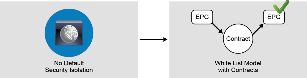
I don’t think this is the best thing to do. Security, all right, so when it comes to security in traditional networking, we’re following the black list security model.
What is that blacklist thingie? It’s like, everything is permitted until I feel that I want to deny certain things. So it’s just like thinking about, I want to be safe from any kind of theft. So I don’t want someone to steal my place, or like to rob my place.
So what’s going to happen there is I’m going to leave all the doors open, and then when the thief is in there, I’m going to capture him.
That’s not how it works, you know. You should actually secure yourself so that the thieves don’t come in, right? So again, we’re still talking about issues and challenges.
What else? What do you expect in the data? How many teams do we have in the data center? We have the network admins.
some people there that are responsible for the servers, the server administrators. people that have to do with VMs and virtual machines, a bunch of different teams that are working together, which is a good thing.
But when it comes to applying a certain task and doing a certain project that is related to different teams, it takes a lot of time to coordinate.
Is it possible to really do it from one place by running some kind of one-man show, for example, where someone can just take over and do everything and finish the job?
Maybe.
And then finally and most important piece of them all, how much time does it take you to configure and implement and bring up a data center?
What I mean by this is if you have a brand fresh green field data center and you want it configured, how many months will it take you to implement it, to initiate and finalize this project?
And the challenge here is the number of devices, the repetition, the number of times you need to connect as a network, and a data center engineer to each and every device and keep configuring and repeating the same configuration over and over and over again.
We want to solve all these issues.

And something that will overcome all of this and we’ll give you a very solid solution that will try to tackle all these challenges is, if we try to know about an architecture, an open architecture by several vendors and several companies around the world that discovered something called software defined networking.
What about software-defined networking?
I want to isolate.
I want to abstract.
What exactly do you want to abstract?
The physical infrastructure from the topmost applications and software that run on top of them, and when we say this, we are really moving towards the virtualization concept where you have some servers and some machines running but instead of having a certain operating system insert a software on top of that physical server, you have several.
You have multiple. The exact same concept, but this time with networking devices, not with just random servers.
So you might have your physical infrastructures there, which is made up of data center devices.
What are they? Switches, different kind of switches. You connect them together. But again, I’m trying to run away from all these problems.
So what do you want to do here? I don’t want to keep connecting to each and every device singularly. So I want to abstract the operating system the way I manage these devices and take it out somewhere else where I can centrally access only that single appliance.
And from that single controller, I would call it a controller, I’ll be able to control each and every device in my infrastructure.
How many devices would I have there? Any number. It doesn’t matter, two, three, tens, hundreds of switches in the infrastructure.
I will always log into my controller, and I’ll be able to manage these in a few minutes. Oh, OK, that’s impressive.
But actually, what do you want to do? How do you want to control this? How do you want to access that controller that you’re talking about?
Well, actually there is an application. There are different kinds of softwares that you might use in order to be able to interact with the controller itself.
So you choose the easiest way in order to communicate with your controller. And I think the easiest way that you might be comfortable with is GUI.
And when we say GUI, we’re really talking here about clicking on a certain icon and just performing a few clicks in a web browser in order to be applying certain commands and applications, instead of having to just apply all these CLI commands one-by-one to every device. You know what? I just have one interface, one GUI. Click, a few clicks, and then it gets translated to CLI.
And then it gets pushed to as many devices that I could have.
Wait for a second, who’s going to be doing this translation? There must be some kind of language, the intermediary language that tries to translate between all these clicks that you do in the GUI and converted to some kind of CLI that will be pushing those devices.
Because again, at the end of the day, the devices do not understand anything except the CLI commands, OK?
So what does that translator look like? It’s something which is called the API, the Application Programmable Interface. This is a generic model. This is something that is being implemented by every single company that needs to create a software defined networking solution.
What did Cisco do in order to be present in this place, in this world of software-defined networking?
We applied this in the data center by creating what we call the ACI, the Application Centric Infrastructure.

Do you remember what we just said? Centralized controller, managing different kinds of devices in the data center, trying to automate those– wait for a second, automate?
Yes, that’s what we’re looking for.
We’re trying to save your time by not having to log into all these devices at the same time and taking a lot of time configuring and troubleshooting. And so access that controller. What you call that controller? The APIC.
So ACI is actually a bunch of data center switches.
To be specific, Nexus 9000 Series switches centrally managed by a controller called the APIC, the Application Policy Infrastructure Controller that will enable us to do what?
To solve all these problems that we were talking about in the traditional networking environment and the traditional data center, such as automation, taking it easy by configuring a bunch of devices at the very same moment, APIs that will program your devices instead of having to seal I, each and every command there.
Just click on the GUI icons, and then it’s going to translate that to you.
And not just this, you can integrate with other partners so that your solution, your data center will be open to the other world.
Any kind of application that you might need to extend your data center with. Security, blacklisting is not that efficient.
I want to work with something better. Whitelisting, everything is denied until I permit you. Very good, what else?
Work mobility, and in the traditional data center, it’s not about physical servers anymore.
We have virtual machines. And when we talk about virtual machines, there are some features where those virtual machines will move from one host to the other.
Is your data central really ready? Is your network infrastructure in that data center ready for this kind of mobilities, for this kind of movement, from one place to the other, from one host to the other?
And then the centralized controller, the APIC that will facilitate everything and answer all the solutions.
And the topology that we were talking about, are we still sticking to the hierarchical network design, the access aggregation core, or do we need to migrate and move to a better, simpler, and easier topology that is called a spinal leaf, two layers only of a routed Layer 3 fabric.
Thank you, no spanning tree. Bye, bye. It’s done. This is ACI. These are the benefits.
As traditional IT departments are under pressure to provide more agility and better outcomes to the business, a new model for operations has emerged, which is called Fast IT.
Cisco ACI enables Fast IT by providing a common policy-based operational model across the entire Cisco ACI-ready system. Fast IT drastically reduces cost and complexity.
In the data center, Cisco ACI is a holistic architecture with centralized automation and policy-driven application profiles.
Cisco ACI delivers software flexibility with the scalability of hardware performance that provides a robust transport network for today’s dynamic workloads.
Cisco ACI is built on a network fabric that combines time-tested protocols with innovations to create a highly flexible, scalable, and resilient architecture of low-latency, high-bandwidth links.
This system-based approach simplifies, optimizes, and accelerates the entire application deployment life cycle across the data center, WAN, access, and cloud environments.
In doing so, this system empowers IT to be more responsive to changing business and application needs. This ability enhances agility and adds business value.
Main components of Cisco ACI:
- Spine switches:
- Represent the backbone of the ACI fabric
- Connected to leaf switches
- Leaf switches:
- Represent connection point for end devices, including APIC
- Connected to spine switches
- Application Policy Infrastructure Controllers (APICs):
- Unified point of policy enforcement, health monitoring, and management for the Cisco ACI fabric
- Not involved in data plane forwarding
Key benefits of Cisco ACI:
- Automation of IT workflows and application deployment agility
- Open APIs and a programmable SDN fabric, with 65-plus ecosystem partners
- Security through whitelisting, policy enforcement, microsegmentation, and analytics
- Workload mobility at scale for physical and virtual load
The design of Cisco ACI is based on the fabric as a whole, as opposed to treating the fabric switches individually. All the physical components form the overall system.
Resolving Challenges of Traditional Network with Cisco ACI – 300-620 DCACI
Look at the following challenges of a traditional network and how Cisco ACI can resolve these challenges.
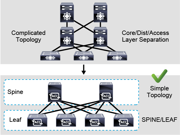
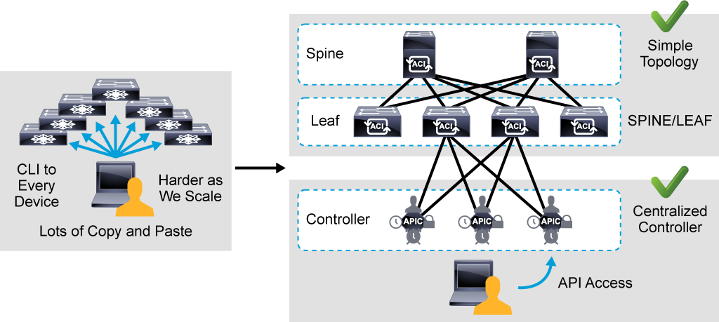
The first challenge of a traditional network is a complicated topology. Usually, traditional networks use traditional core-aggregation-access layers. When you add more devices, this topology can be complicated to manage.
In the Cisco ACI, a spine-leaf topology is used. All the connections within the Cisco ACI fabric are from leaf to spine switches, and a mesh topology is between them.
There is no leaf-to-leaf and no spine-to-spine connectivity. Leaf and spine topology is the basis of the Cisco ACI architecture.
The physical devices that are used in Cisco ACI Fabric are Cisco Nexus 9000 switches.
Compared to switches used in NX-OS mode, the difference is that the software used in ACI mode is the ACI operating system.
Therefore, although the hardware may be the same, Cisco ACI provides a completely different product. Cisco ACI is not a feature of Cisco Nexus.

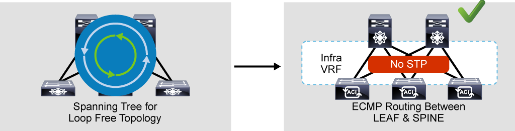
The next challenge is avoiding the loop between layer 2 devices. Traditional networks rely on the Spanning Tree Protocol (STP).
In Cisco ACI, you do not rely on STP between leaf and spine switches; Equal Cost Multipathing (ECMP) is used instead.

Since there is IP reachability between leaf and spine switches, there is no need for STP, and you do not have to block any port to avoid the Layer 2 loops.
From security perspective, in a traditional network device, you usually allow all the traffic by default, or you explicitly configure the device to block the traffic.
However, in Cisco ACI, a whitelist model is used. By default, everything is blocked, unless you explicitly allow the traffic.
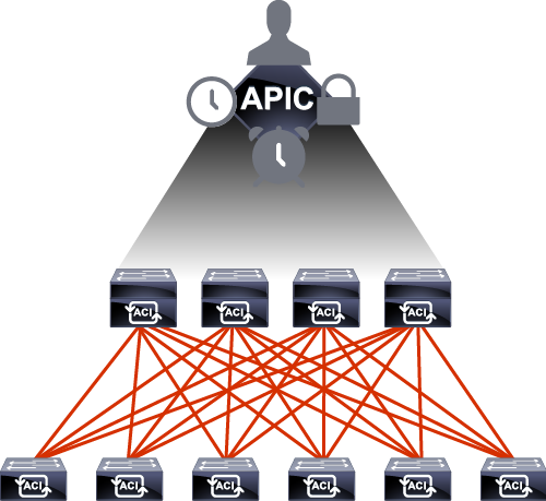
Another challenge is device management. There can be tens or hundreds of devices, also in a leaf and spine topology.
Instead of using SSH to each and every device to configure and build the Cisco ACI fabric, there is a centralized controller called APIC.
You can still directly access the leaf and spine switches but you cannot configure anything directly on them. You always configure your Cisco ACI fabric from the Cisco APIC.
In Cisco ACI, there are typically three Cisco APIC controllers and they form an APIC cluster.
If you lose one of them, you can still change and add new configurations through the remaining two controllers.
If you lose all three, your traffic flow will not be impacted because the configurations are already pushed to the leaf and spine switches. So even if all the controllers are down, forwarding still happens on the leaf and spine switches.
If you want to add changes, you must bring the Cisco APICs back up. Cisco APIC is simply a controller to push the configuration—it is not in the forwarding or data plane.
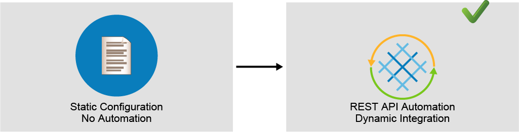
Another very important point in the Cisco APIC is that it enables access via Cisco API. In the Cisco ACI, all configurations can be represented by policies and objects.
These policies and objects can be stored in the XML or JavaScript Object Notation (JSON) format. Policies and objects can be easily accessed via API or configured via API.
In traditional network usually there is no automation and configuration is done manually and statically.
In Cisco ACI, by using REST API calls it is easy to automate configuration.
It is also possible to provide dynamic integrations where you can dynamically communicate and push the configuration to another vendor’s controller, VMware vCenter server, for example.
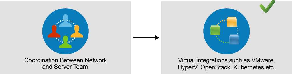
Dynamic integration also helps with the last challenge: coordination between network and server team.
Typically, network and server teams are two different teams. They need to cooperate to make sure that, for example, the new service has correct security rules, correct VLAN, and that correct VLAN is deployed in the correct place.
Sometimes, communication is not an easy task.
By using the dynamic integration, for example, VMware integration, you can dynamically push the configuration to the vCenter Server.
Then you can verify that the network (ACI) side has the configuration deployed, and also that the server side has the mapped configuration.
Introducing Cisco ACI Fabric Infrastructure and Basic Concepts
Cisco ACI Topology and Hardware – 300-620 DCACI
ACI hardware and topology.
The two different topics here are smaller topics that we can discuss at this very same time because, at this point, we are trying to know more about the hardware.
We’re trying to know more about the switches that will make up this ACI fabric.
When I say fabric– you’re going to hear this word a lot– it means the data center, the network that is made up of the ACI switches. So it’s actually the Nexus 9000 Series switches.
The thing about the Nexus 9K or the 9000 Series switches is that we have several flavors from this switch.

We have either the Nexus 9500 or the 9300. So you want to know more about the speed of this switch and how fast it can actually forward your traffic in the ACI.
So we want to know the speed, and we want to know the position. Where do we place these two different kind of switches?
So, as you can see here, we have the 95. The 95 will give you speeds that range from 10 gigabit per second until it reach all the way up to 400 gigs. 400. You’ve heard that right.
400. And not just this– it’s a modular switch. What do I mean by the modular switch? It does have line cards. So if you want to have a line card that is 10 gigs, another line card that has 100 gigs, and a mix of different kinds of line cards, you can do that with the 9500 series.
So we have a switch that is 4 slot, 8 or 16 slots, and you have to choose your line cards, of course.
So there are certain special line cards for this, some line cards which are ACI specific, and some line cards which will not run in the ACI mode.
Hey, wait a second.
The Nexus 9k does not always run ACI. So once you buy them, you want to make your mind, like, are you buying these switches for the ACI or do you want to just run them normally in a traditional network environment?
End of the day, it’s a switch and it will accept the CLI command, so you have to make your choice.
So here what we’re talking about is once you choose the 9500 series switch, its line cards has to be the 9500 series line cards that will support ACI.
What about the 9300s? Well, that’s the smaller guy that will function as a leaf. What is that thing that you just said, “leaf?” Are you trying to tell me something about the topology that you will try to connect these different switches through?
Yes, that’s the thing, and that’s something that we’re going to discuss in a few minutes from now. But just let’s first wrap up with the different kinds and then we can talk about the topology.
So here, the 9300 is actually the smaller guy that has speeds which are similar to the 95, the big brother there, however, it can be playing a different role. This is the switch that we will connect to the end users, to the servers.
That’s where the number come from the 9300. It’s like the smaller friend.
So let’s lay the spotlight on the 9500 series switch, and here we’re talking about the one with the 8 slots.
OK. Eight line cards. So different line cards, as we said, ranging speed– ranging from 10 to 400 gigs, and we have some other modules in there which are really important.
And the most important one of them all, the one at the bottom here, the supervisor module.
We have a couple of them, which is actually the brain of that switch, and we have something which is assisting, some other module which is assisting the supervisor.
Who is that guy? It’s the system controller. Something very unique to the 9500 series. It’s something that it’s a module that offloads the– some of the control traffic from this specific switch.
We also have the fan trays. And when I say fan trays, it’s a combination of different fans in a single tray.
Behind the tray– behind the fan tray, that’s something that is not visible from this picture, but if you remove the fan tray, you’re going to find your fabric modules.
What is that fabric module? It’s when you try to interconnect the different slots, the different line cards together.
Like you might ask me a question. If the traffic is being received from one port of the line card and it’s being forwarded to another port on another line card from the very same switch, what does it cross in the middle?
It crosses the fabric module. It does have another name, by the way. It’s called the crossbar. So whether it’s fabric module or crossbar, the same thing.
This is the 9500, and it runs with a power supply, not just a single one. You know, we have several power supplies for redundancy that work with N+N or N+1.
What about the 93? The 93 can play two major roles at the same time, spine or relief. Again, I keep hearing words that I’m not aware of, but it’s coming. It’s coming in the topology in a few seconds from now.
So the 9300 switch, the smaller guy, you know. It is small in size, but it has the same speeds. You know, we’re still talking about 10, 40, 100, or 400 gigabit per second. Same thing. So we have different flavors here.
But this guy– you need to remember one thing. It’s a fixed switch. It’s not like the 9500. You cannot adjust it.
You cannot remove the modules from there. It’s just– it’s one piece. It comes this way. It is fixed.
So you have the 9364, the 9332, 36 and the 9316. And the last two digits represent the total number of cores of a specific switch.
For example, the 9364, 64, that number in there represents the total number of ports.
The 93, still, we’re talking about the same guy, but acting as a leaf switch. That’s going to be a bunch of other options. 9336C, the 93180LC and then we have the 9332PQ.
What are those names, spine, leaf? I keep hearing them. That’s why we need to discuss the topology.
How do we connect those devices together? And that’s the most important piece here because you don’t want to connect them in such a way that are similar to the traditional network design.
There is a specific topology, a specific design, to connect these devices, and we call this design the spine and leaf design. Two layers.
Just two layers. A layer of leaves, which will be facing the end-users and servers, and a layer of spines, which will only be facing the downstream leaves.
Leafs can never be connected to leafs. They only get connected to spines and spines only connect to leafs.
OK. So we don’t have cross connectivity from the same layer. That’s a very important piece of information.
Redundancy is all there. So when it comes to spines, we can have two spines, at least, and then we can increase it to as many spines as you get.
It’s not as many, but it’s a specific number, we’re going to say 16, to be very specific.
The end devices, again, only and only get connected to the leafs. This kind of topology make it really easy and simple for the devices to discover one another. It enables a very important topology that has multi-pathing there.
Every single switch has the exact same number of hops to forward traffic from one source to the other destination.

So if I were to ask you a question here, how many hops away– if you wanted to send some traffic received by the leaf switch on the very far left hand to the leaf switch on the very far right hand, the answer is going to– we take a pause for a few seconds, then you can answer it. And it’s going to be the exact same answer if another pair of switches worked for traffic. Two, right? Two hops away. That’s easier for troubleshooting.
This is why we needed to eliminate the hierarchical network design.
Topology, hardware. You now know the boxes. You know how to connect them.
DCACI – Cisco Application Centric Practice Test
300-620 Cisco Data Center ACI Implementation Questions & Answers
Description
(The Implementing Cisco Application Centric Infrastructure v1.0 (DCACI 300-620) exam is a 90-minute exam that is associated with the CCNP Data Center Certification and Cisco Certified Specialist – Data Center ACI Implementation certifications.
This exam tests a candidate’s knowledge of Cisco switches in ACI mode including configuration, implementation, and management.
The course, Implementing Cisco Application Centric Infrastructure (DCACI), helps candidates to prepare for this exam
Available Number of Questions are 50
Exam Number : 300-620
Exam Language : English
Exam Name : Cisco Data Center ACI Implementation
Duration : 90
Passing Score : 800 Minimum out of 1000
1 – ACI Fabric Infrastructure
Describe ACI topology and hardware
Describe ACI Object Model
Utilize faults, event record, and audit log
Describe ACI fabric discovery
Implement ACI policies
- access
- fabric
Implement ACI logical constructs
- tenant
- application profile
- VRF
- bridge domain (unicast routing, Layer 2 unknown hardware proxy, ARP flooding)
- endpoint groups (EPG)
- contracts (filter, provider, consumer, reverse port filter, VRF enforced)
2 – ACI Packet Forwarding
Describe endpoint learning
Implement bridge domain configuration **** (unicast routing, Layer 2 unknown hardware proxy, ARP flooding)
3 – External Network Connectivity
Implement Layer 2 out (STP/MCP basics)
Implement Layer 3 out (excludes transit routing and VRF route leaking)
4 – Integrations
Implement VMware vCenter DVS integration
Describe resolution immediacy in VMM
Implement service graph (managed and unmanaged)
5 – ACI Management
Implement out-of-band and in-band
Utilize syslog and snmp services
Implement configuration backup (snapshot/config import export)
Implement AAA and RBAC
Configure an upgrade
6 – ACI Anywhere
Describe multipod
Describe multisite
Included in This Course50 questions practice Tests
- 300-620 Practice Test 131 questions
- 300-620 Practice Test 219 questions
Now, we’re ready for the next step, what is running in that fabric?
It’s time for the protocols. It’s time for you to understand what kind of protocols are running in there between these devices in the ACI fabric. We have IS to IS routing protocol. We have VXLAN, LLDP, and DSAP. In this lesson we’re going to talk about IS to IS and VXLAN. In the next one we’re going to talk about the DSAP and LLDP.
So why IS to IS, and why VXLAN? And what is the relationship between these two? There is no relationship whatsoever.
But what I need you to understand at this point is we have a bunch of devices that are being connected now in a certain topology, and they need to discover one another as neighbors.
Go and use spanning tree. We’ve already established that we’re not going to touch spanning tree.
Why? Because with spanning tree, you’re blocking a few links. And I need all my links up and running in order to achieve what? Load balancing.
I want all of them to be pushing traffic at the same time. That’s not going to happen unless you run a routing protocol.
And this routing protocol here is the IS to IS routing protocol. So your fabric, your ACI fabric is Layer 3.
Now, what’s going to happen is the different spines and the different leaves will need to learn each other addresses, the IP addresses that will be allocated to them. By who, who’s allocating IP addresses to those devices? We’re going to see that in the next topic. That’s going to be the APIC trying to lease DSCP IP address to those different devices in the fabric.
Once they are being leased, every single device has its own ID, has its own loopback IP address, then they need to be advertised using a routing protocol the same way you used to do it with the routing protocols.
You know what? You have an IP. You have an identity, I would say. You need to just route it to the next and next and next neighbor so that all the devices in your fabric will know about the presence of the other devices.
Why? I’m trying to get them ready to forward traffic so that when they start forwarding traffic, they know how to reach one another.
Every single device knows its path, knows its way to the final destination. And the good news is we’re going after ECMP. What’s that?
Equal cost multi pathing, which is going to take the packet, the traffic that you’re going to forward– the switches are going to look at the source destination IP address, source and destination port or protocols and be able to make the load balancing that we are talking about.
So once again, why IS to IS? Because we want to achieve Layer 3 reachability between these different devices.
So now that we have built the fabric, now that we have routing protocol running, and now that all the devices can reach one another– the switches, the spines and leaves, they know about the presence of one another, and they have their IP addresses in their routing table. So what are we expecting next? We’re expecting traffic to flow. Where is traffic coming from?
Traffic is coming obviously from the servers, endpoints that are connected where? Do you remember? Take a pause, a few seconds. They’re all connected to the leaves, exactly. We would never connect servers to the spines.
So how are you going to forward your traffic, and what happens if one of those servers– let’s assume that that’s a virtual machine, for example. You decided to move it to another leaf. What do you mean, decided to move it to another leaf?
Yeah, migrate it. It was plugged into that very left-hand side leaf switch, and then suddenly you decide to just plug it to the next switch for any kind of reason for any kind of feature that you might have in your hypervisor that is connected in there,
so maybe some kind of virtual machine mobility took place. You need to address a very important point over here. The coupling between the end point, which is, in this case, our VM, and the leaf switch– you’re always– in a traditional network environment, the physical device is always tied to the gateway, to its gateway.
If you move it, you have to change the IP address of the gateway because that’s another physical device that you got connected to.
This is why we need to form an overlay.

This is why we need to run some kind of protocol that decouples endpoint location from the physical infrastructure. This is why we need to cheat– yeah, exactly, you heard me right, cheat– on the servers by letting them know that wherever they go, it’s going to be the exact same leaf they’re connected– it’s going to be the exact same gateway they’re connected to.
It’s going to be some technology, which is called VXLAN, Virtual Extensible LAN. I’ve heard that thing before. You know, I’ve heard VLAN, but now you just added an X. What is the extension?
Where is the extension coming from? And I might ask you a question. How many VLANS, how many maximum VLANS you would think about when we just say VLAN? 4,096, exactly.
But now, when you say extend, what do you think the number would be? 16 million VLANs. We’re talking about modern data center that will have hundreds and hundreds of VMs, and we need these data centers to be ready. So this is one of the reasons we need to run this technology, this Layer 2 technology.
Wait a second, I’m actually getting confused here. Layer 2 on top of Layer 3, what is happening here?
Yes, we’ve already run Layer 3 IS-IS. The main purpose of that was for the spines of leaves to be neighbors. Now we’re running Layer 2 on top of that for the sake of fabric traffic forwarding so that whenever you’re pushing any kind of traffic, VXLAN– the most important thing about it here,
it’s never going to look at the traffic itself. It’s going to always double encapsulate your traffic with a VXLAN external header and push it in your fabric.
The only question that will remain for the devices to be able to forward traffic, do you know how to reach your neighbor device,
yes or no?
But you don’t want to worry about what you’re carrying. So whether you’re actually trying to push some kind of GRE traffic, whether it’s normal Ethernet traffic, double-tagged Ethernet traffic with two tags– again,
the main point here is the fabric really doesn’t care about the traffic that it receives from the endpoints, from the servers. It takes it as it is.
It does something which is called normalization that is actually adding that extra piece, that header, that VXLAN header.
How big is that header, by the way? 50 bytes in size that will give relevance to that traffic from the prospect of the leaves.
For the leaves to be able to forward traffic, I need to understand where exactly should I push my packets.

So in that traffic, in that header, in that 50-byte header, you’re going to have your source and destination leaf IP address.
So we don’t call them leaves anymore because spines and leaves are from the perspective of the topology.
We’re not talking about an overlay protocol. We’re not talking about another function that will be added by VXLAN. What is that function? It’s called a VTEP, a virtual tunnel endpoint. So every switch, when it receives the traffic, it needs to know the next VTEP to be able to push that traffic towards it.
On the way out, the receiving switch is going to have to localize the traffic to its original format.
So remember that 50-byte header? We don’t need it anymore because the end users, the host, they don’t understand VXLAN. They don’t need to do anything with that 50-byte header.
So please, Mr. VTEP, virtual tunnel end point, on the way out, try to de-encapsulate- or in other words, try to localize your traffic back to its original format– so that the host, the servers, will receive it as is. And they won’t have to worry about understanding that kind of protocol.
These are the first two protocols that you need to learn and understand about ACI that are running there in the ACI.
The good news is you don’t need to worry about configuring them. They are there by default, and they’re automated.
Wait, how did this happen? You remember the APIC? Remember the automation? Everything is taken care of without you having to touch anything.
Not literally you don’t have to touch anything, but you have to just go with minimal configuration and then, boom, watch the magic happen.
These are the two most important protocols that are running there in the ACI fabric.
Now let’s add some more protocols that will help in the discovery process in the next lesson.
How do we configure and monitor your Nexus 9000 series switches?
In other words, do you want to manage your ACI fabric from a central appliance? Well, meet the Cisco APIC– Application Policy Infrastructure Controller.
The name itself gives us an overview of what it does. It is a policy controller that relays the intended state of the policy to the ACI fabric.
It does a lot of things, and we need to list them down. It defines policies and pushes them to the ACI Nexus switches.
It represents the management plane only and not the control plane, which means also it is not located in the traffic path.
And the way to deploy it is in a redundant cluster of servers.
The Cisco APIC is an appliance that comes in two form factors depending on the amount of configuration that could be pushed to the Nexus 9000 series switches.
Originally, it is a UCS C220 or C240 M5 server that can also be called APIC M3 or APIC L3, where M stands for medium and L is large.
And we are talking here about the configuration size. It can support 1,000 or more than 1,000 EdgeSwitch ports depending on the physical specification. If we dig deeper,
then you will know that the APIC software is delivered on a Cisco UCS server appliance with an SSL certificate that allows the hardware to run that software. The product consists of the server hardware and pre-installed Cisco APIC software.
So what about redundancy? Well, the APIC is redundant on the interface level as well as the cluster level.
From interfaces perspective, the APIC has two types of interfaces– bond0, which is the port used to connect the APIC to the ACI fabric.
You do that if you connect a pair of bond0 links to two leaf switches, one as active and another as standby, or maybe you want to go for a VPC. The second interface is bond1, which is used for out of band management.
On the cluster level, it gets more interesting. We always deploy a cluster of at least three APIC controllers.
Should your ACI fabric deployment grow, then you will need more APICs that could be in odd numbers– three, five, or seven.
The reason behind the odd numbers lies behind the data replication process done by the APIC.
Let’s talk more about this. To support a greater scale and resiliency, Cisco ACI uses a concept known as data sharding for data stored in the APIC.
The theory behind sharding is that the data repository is split into several smaller database units known as shards.
Data is placed in a shard, and that shard is then replicated three times, with each replica assigned to an APIC appliance.
If one APIC were to fail at any moment for any reason, two remaining replicas will form a majority to prove that the data is not corrupted and could be accessed, and configuration can still be performed.
Where if you lose the majority, in this case you are only left with one APIC if we’re talking about a cluster of three, for example.
Then you will not be able to configure your ACI fabric.
On top of the three APICs in a small cluster, you can actually add a fourth APIC that could act as a cold standby server.
In our example, the cluster made up of three, the designated active APICs share the load.
And the standby APIC, the fourth one, can act as a replacement for any of the APICs in that active cluster.
That standby APIC does not participate in policy configuration or management whatsoever until you decide to manually power it on and let it join the cluster, only if an active APIC were to fail.
And this is how your ACI fabric is centrally managed from this server, the APIC.
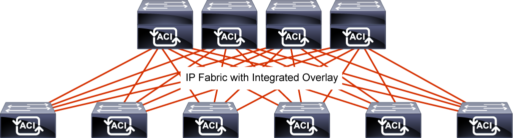
Cisco ACI fabric uses a spine-leaf topology.
High-bandwidth links between the spine and leaf switches provide transport to an integrated overlay.
The host traffic that arrives at the ingress leaf and needs to be sent to an egress leaf is carried over an integrated overlay.

All-access links from endpoints are attached to the leaf switches, which provide a high port density, while the spine switches (minimum of two spine switches for redundancy) aggregate the fabric bandwidth.
Sometimes, the traditional model of Multi-tier is still required.
The primary reason for this is cable reach, where many hosts are located across floors or across buildings; however, due to the high pricing of fiber cables and the limitations of cable distances, it is not ideal in some situations to build a full-mesh two tier Clos fabric.
In those cases, it is more efficient to build a spine-leaf-leaf topology and continue to benefit from the automation and visibility of Cisco ACI.
Starting with the Cisco APIC Release 4.1(1), you can now create a Multi-tier Cisco ACI fabric topology that corresponds to the core-aggregation-access architecture.
The new design for Cisco ACI incorporates the addition of a tier-2 leaf layer for connectivity to hosts or servers on the downlink ports and connectivity to the leaf layer (aggregation) on the uplink ports.
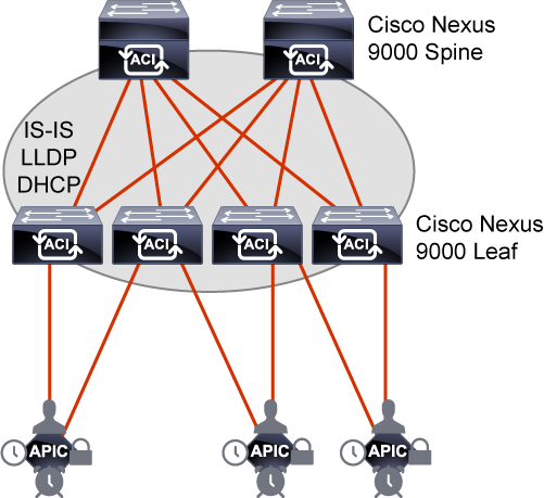
The Cisco ACI fabric is composed of the Cisco APIC and the Cisco Nexus 9000 Series spine and leaf switches.
The leaf switches are connected to the spine switches, but never to each other.
The spine switches are attached only to the leaf switches.
The Cisco APIC and all other endpoints and devices in the data center are connected to the leaf switches only as seen from the following figure.

With Cisco ACI, APICs manage the infrastructure IP address space and automatically allocate proper IP addressing required for the leaf and spine.
The infrastructure IP addresses are in a separate virtual routing and forwarding (VRF) than the user data traffic
so that the infrastructure IP is contained within fabric and won’t have any overlapping IP address issues.
The infrastructure VRF is transparent to external traffic. You specify this IP address range, which is called tunnel endpoint (TEP) pool, during the Cisco APIC initial configuration.
Time synchronization plays a critical role in the Cisco ACI fabric.
It is important for proper analysis of traffic flows and for correlating debug and fault timestamps across multiple fabric nodes.
The Cisco ACI fabric must be configured with an active Network Time Protocol (NTP) policy to assure that the system clocks on all devices are correct.
Atomic counters that are used to detect drops and misrouting in the fabric also require an active fabric NTP policy.
Spine-Leaf Topology Benefits
By using a spine-leaf topology, the fabric is easier to build, test, and support. Scalability is achieved by simply adding more leaf nodes if there are not enough ports to connect hosts, and adding spine nodes if the fabric is not large enough to carry the load of the host traffic.
The symmetrical topology allows for optimized forwarding behavior, needing only two hops for any host-to-host connection.
The design allows a high-bandwidth, low-latency, low-oversubscription, and scalable solution at low cost.
In summary, the advantages of the spine-leaf topology include:
- Simple and consistent topology
- Scalability for connectivity and bandwidth
- Symmetry for optimization of forwarding behavior
- Least-cost design for high bandwidth
IS-IS Fabric Infrastructure Routing
The fabric applies a densely tuned Intermediate System-to-Intermediate System (IS-IS) environment utilizing Level 1 connections within the topology for advertising loopback addresses.
Loopback addresses are the Virtual Extensible LAN (VXLAN) Tunnel Endpoints (TEPs) that are used in the integrated overlay and advertised to all other nodes in the fabric for overlay tunnel use.
IS-IS is responsible for infrastructure connectivity in Cisco ACI:
- IS-IS provides IP reachability among TEP addresses
- Automatically deployed, no user intervention is required
- No IS-IS knowledge is required

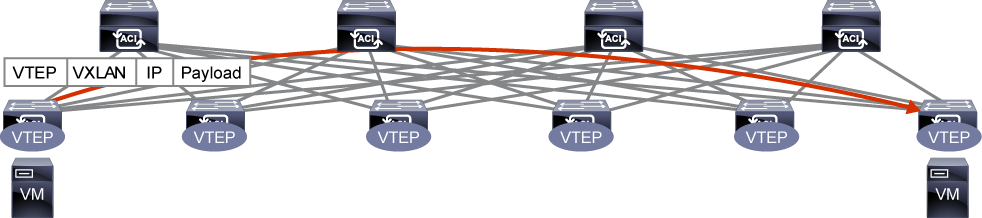
Endpoint Forwarding Across Leaf Switches – 300-620 DCACI
When a packet is sent from one leaf to another, an end host (called an endpoint in ACI) location is identified by a TEP IP of each node.
User data traffic is encapsulated with VXLAN header when being forwarded to another leaf.
The forwarding across switch nodes is performed based on the TEP IP in the VXLAN encapsulation.
In case the ingress leaf is not aware of the destination endpoint location (TEP), ACI has a distributed database called Council of Oracles Protocol (COOP) on each spine that knows all the mapping of endpoint and TEP.
Deployment Options
Organizations are always trying to ensure proper alignment between IT capabilities and different business requirements (size and scale) that create disparate demands on data center networks.
On the other hand, the needs of massively scalable data centers, service provider cloud solutions, and the mass market are very different.
A single organization may have multiple data centers, each with different requirements and business usage.
For example, a cloud service provider can have its own data center infrastructure for internal operations and another infrastructure for its customers’ cloud services.
The data centers may be positioned in a single location, in multiple floors or buildings, or in multiple locations that need to be interconnected.
The following tables list the major deployment types.
| Topology | Cluster | Description |
| Multitier | Single | A solution that corresponds to the core-aggregation-access architecture.Additional tier-2 leaf layer for connectivity to hosts or servers on the downlink ports and connectivity to the tier-1 leaf layer (aggregation) on the uplink ports.The primary reason for this is cable reach, where many hosts are located across floors or across buildings; however, due to the high pricing of fiber cables and the limitations of cable distances, it is not ideal in some situations to build a full-mesh two tier Clos fabric. |
| Multipod | Single | A solution to manage multiple pods (such as multiple floors or buildings) as a single ACI fabric from the same APIC cluster.Each pod has at least one spine and one leaf. |
| Topology | Cluster | Description |
| Remote leaf | Single | A solution to deploy a few physical leaf switches to a satellite branch as a small but direct extension of the main ACI fabric without having to setup the whole spine-leaf architecture as a new pod. |
| vPod | Single | A solution to deploy one of the ACI pods in a virtualized setup without physical leaf and spine switches.vSpine and vLeaf are VMs in VMware vSphere.Cisco ACI Virtual Edge (AVE) handles forwarding and policy enforcement. |
| Multisite | Multiple | A solution to manage multiple ACI fabrics from a single point of controlEach ACI fabric is referred as a site and typically located further away to each other than multi-pod.Each site is a single ACI fabric with its own APIC cluster. An orchestrator called Multi-Site Orchestrator (MSO) is used to manage those sites. |
Cisco APIC – 300-620 DCACI
Cisco APIC is a policy controller.
It relays the intended state of the policy to the fabric.
The APIC does not represent the control plane and does not sit in the traffic path.
The hardware consists of a cluster of three or more servers in a highly redundant array.
Cisco APIC has these roles:
- Is the policy controller
- Holds the defined policy
- Represents the management plane
- Not the control plane
- Not located in the traffic path
- Instantiates the policy changes
- Is deployed as a redundant cluster of servers
The Cisco APIC appliance has two form factors for medium or large configurations.
Medium configurations have a medium-size CPU, hard drive, and memory for up to 1000 edge ports.
Large configurations have a large-size CPU, hard drive, and memory for more than 1000 edge ports.
A Cisco APIC appliance comprises either a cluster of Cisco Unified Computing System (UCS) C220 or C240 M5 as third-generation appliances (which are referred as Cisco APIC M3 or Cisco APIC L3, intended for medium or large configurations), Cisco UCS C220 or C240 M4 (Cisco APIC-M2/L2) as second-generation appliances, or Cisco UCS C220 or C240 M3 (Cisco APIC-M1/L1) as first-generation appliances.
The Cisco APIC software is delivered on the Cisco UCS server appliances with an SSL certificate that allows the hardware to run Cisco APIC software.
The product consists of the server hardware and preinstalled Cisco APIC software.
Since the hardware is UCS C-Series, it comes with Cisco Integrated Management Controller (IMC).
Make sure CIMC is running a compatible version from an APIC release note as well.
Cisco APIC Redundancy – 300-620 DCACI
Cisco APIC is redundant on multiple levels, including interface-level and cluster-level.
Cisco APICs use a bonded interface that is typically dual-homed to two leaf switches for connectivity to the Cisco ACI fabric, and have the ability to use a bonded interface that can be dual-homed to the out-of-band management network. There are two bond interfaces:
- Bond0 is used to connect to the fabric itself (to connect to leaf switches that connect into the fabric). It is recommend connecting two fabric uplinks, each to a separate leaf and/or vPC Leaf pairs.
- Bond1 is used to connect to the out-of-band (OOB) segment (that allows setup of the APIC itself).
The following figure depicts the Cisco APIC M3/L3 server rear panel, indicating the Bond0 on the Cisco UCS VIC 1455 card with 4 external 10/25-Gigabit Ethernet ports and Bond1 on the dual 1-Gb/10-Gb Ethernet ports.

Depending on your CIMC settings, CIMC can be accessed through the 1-Gb/10-Gb Ethernet LAN ports or the Cisco VIC, or through a 1-Gb dedicated management port, which is also present on the controller.

The four ports on the Cisco UCS VIC 1455 are paired in the following manner: port-1 and port-2 (from left to right) represent one pair, corresponding to eth2-1 on APIC and port-3 and port-4 is another pair, corresponding to eth2-2 on APIC. Eth2-1 and eth2-2 form the Bond0, which is an active/standby Port Channel.
Only one connection is allowed for each pair. For example, you can connect one cable to either port-1 or port-2, and connect another cable to either port-3 or port-4 (please do not connect two cables on any pair).
On APIC M2/L2 2-port VIC 1225 is used. In this case, both ports form Bond0 (active/standby mode). One port is connected to one leaf switch and the other port is connected to another leaf switch.

On top of the three (or more) APICs that actively form a cluster, one could have a standby APIC.
The standby APIC functionality enables you to operate the APICs in standby mode. In an APIC cluster, designated active APICs share the load, and the designated standby APICs can act as a replacement for any of the APICs in an active cluster.
The standby APIC does not participate in policy configuration or management. No information is replicated to the standby controllers.
You can configure the standby role when the Cisco APIC is launched for the first time.
You should have at least three active APICs in a cluster, and one or more standby APICs.
There must be three active APICs to add a standby APIC. As an admin user, you can initiate the switch over to replace an active APIC with a standby APIC.
The standby APIC is automatically updated with firmware updates to keep the backup APIC at same firmware version as the active cluster.
Each Cisco APIC controller, active or standby, has an ID that designates it within the cluster.
The ID of a standby controller changes when it switches over to an active APIC. The standby controller takes over the ID of the replaced (previously active) controller while keeping its formerly configured name.
Although an APIC can be replaced without a standby APIC, a standby APIC makes the replacement procedure easier and even more seamless.
Cisco APIC Cluster – 300-620 DCACI
Cisco APIC is deployed in a cluster with a minimum of three controllers.
The ultimate size of the controller cluster is directly proportionate to the size of the Cisco ACI deployment and is based on transaction-rate requirements.
Any controller in the cluster can service any user for any operation, and a controller can be transparently added to or removed from the cluster.
APICs form a cluster and talk to each other using the infra network provided by leaf and spine.
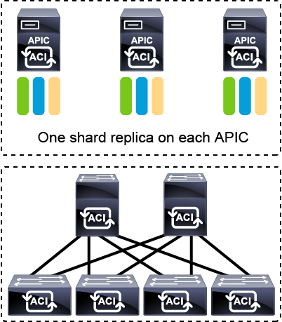
The APIC cluster uses a large database technology called sharding.
The APIC configuration database is partitioned into logically bounded subsets, called shards, and each shard has three replicas.
The shards are evenly distributed across the APICs, while the shard data assignments are based on a predetermined hash function, and a static shard layout determines the assignment of shards to appliances.
This specific database technology provides scalability and reliability to the data sets that are generated and processed by the Cisco APIC.
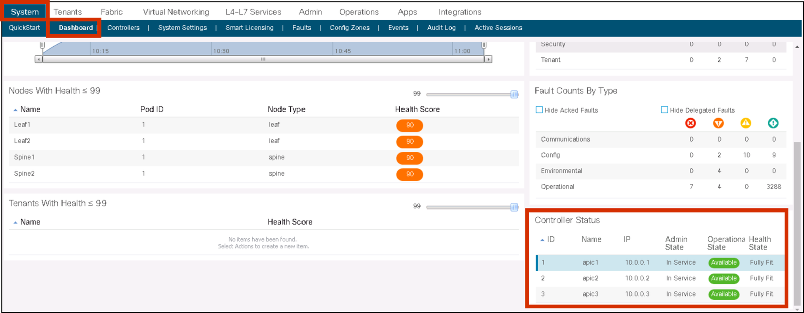
APIC cluster status should always be Fully-Fit meaning all the APICs are healthy as seen in the following figure.
If one or more of the APIC controllers’ health status in the cluster is not Fully-Fit such as Data Layer Partially Diverged, APIC infra communication, or processes on APIC may have some problem and any configuration changes should be avoided until it’s fixed.
When there is an issue in communication between each APIC and it was split in two, such as 2 APICs and 1 APIC for 3 APICs cluster, although it is recommended to fix it first prior to any configuration changes, configuration changes can be performed on the majority side (2 APICs) if it is still Fully-Fit on the majority side.
You should also follow general guidelines when managing Cisco APIC clusters:
- Utilize at least 3 active APICs in a cluster, along with additional standby APICs. A cluster size of 3, 5, or 7 APICs is recommended—a cluster size of 4 or 6 APICs is not recommended.
- Disregard cluster related information on standby APICs since it’s not relevant.
- Cluster slots contain an APIC ChassisID. Once you configure a slot, it remains unavailable until you decommission the APIC with the assigned ChassisID.
- When performing an APIC firmware upgrade, wait for the upgrade process to complete and verify the cluster health before performing other changes to the cluster.
- When moving an APIC, first ensure that you have a healthy cluster. Once the moved APIC is re-connected, verify that all controllers in the cluster return to a fully fit state.
- Since cluster of APICs running different firmware version is an unsupported operation, ensure that all APICs use the same firmware prior to adding them to the ACI fabric.
When managing the Cisco APIC cluster, you can perform different tasks, which require a specific procedure:
- Expanding the APIC cluster size: An operation that increases the configured number of APICs in the cluster, from a cluster size of N to size N+1, within legal boundaries.
- During cluster expansion—regardless of the order for physical connection of the APIC controllers—the discovery and expansion takes place sequentially based on the APIC ID numbers (first APIC1, then APIC2, then APIC3, and so on).
- Reducing the APIC cluster size: An operation that decreases the configured number of APICs, from a cluster size of N to size N -1, within legal boundaries. During cluster contraction, you must begin decommissioning the last APIC in the cluster first and work your way sequentially in reverse order (first APIC4 if it is the last APIC ID, then APIC3, then APIC2, and finally APIC1).
- Replacing an APIC in the cluster: Decommission the APIC that you want to replace, and commission the replacement APIC using the same configuration and image of the APIC being replaced.
- Prepare a cold standby APIC in the cluster: An APIC in a standby mode offers a cold standby.
- At least three active APICs in a cluster and one or more standby APICs are recommended. This option is recommended especially in Cisco ACI Stretched Fabric or Multipod implementations where the possibility of APIC split-brain situation is relatively higher than in other deployment options.
- Shutting down and bringing up APICs in a cluster: When needed, you can shut down APICs in the cluster.
- For example, you can shut down the APIC when moving it to another location. But bring the APIC online as soon as possible, and verify that all controllers in the cluster return to a fully fit state.
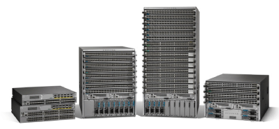
Cisco Nexus 9000 Series Hardware
The Cisco Nexus 9000 Series is the next generation of data center switching infrastructure.
In the Cisco ACI mode, the Cisco Nexus 9000 Series provides the spine and leaf switches that build the fabric.
The Cisco Nexus 9000 Series offers a powerful combination of hardware and software that is custom-developed to provide a robust and comprehensive solution.
Cisco Nexus 9000 Series family consists of these elements:
- Cisco Nexus 9500 Series modular chassis
- 4-slot, 8-slot, and 16-slot
- Support 10GE, 40GE, 100GE, and 400GE modules
- Cisco Nexus 9500 Series line cards
- Cisco Nexus 9300 Series top-of-rack (ToR) leaf and spine switches
- Cisco ACI spine and leaf varieties
- 1/10/40/100/400 GE interface speeds
Note
Cisco Nexus 9200 Series switches only support NX-OS mode, and cannot be used for Cisco ACI.
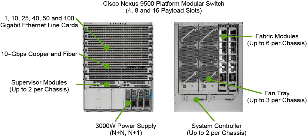
Cisco Nexus 9500 Platform Components
The Cisco Nexus 9500 platform is a modular chassis that supports up to 16 line cards, 2 supervisor modules, 2 chassis controllers, 3 fan trays, 6 fabric modules, and 10 power supplies.
The switch supports comprehensive Layer 2 and 3 functions on nonblocking 1-, 10-, 25-, 40-, 50-, and 100-Gigabit Ethernet ports.
A pair of redundant supervisor modules manages all switch operations. The supervisor accepts an external clock and supports management through multiple ports, including two USB ports, a serial console, and a 10/100/1000-Mbps network port. Redundant supervisors must be of the same type within a chassis.
A pair of redundant system controllers offload chassis management functions from the supervisor modules.
The controllers are responsible for managing power supplies and fan trays and are a central point for the Gigabit Ethernet out-of-band channel (EOBC) between the supervisors, fabric modules, and line cards.
The Cisco Nexus 9500 platform supports hot-swappable, front-panel-accessible AC, DC, and universal AC/DC power supplies. N+1 and N+N redundancy modes are supported depending on the chassis configuration.
The 3000-W power supplies are 80 Plus Platinum-rated, providing more than 90-percent efficiency across typical workloads.
Three hot-swappable fan trays support front-to-back cooling. Each fan tray covers two fabric modules and can be removed for access.
The Cisco Nexus 9500 platform uses a Clos fabric design that interconnects the line cards with rear-mounted fabric modules.
Cloud scale Technology powered N9K-C95xx-FM-E enables 100-Gigabit Ethernet spine deployments.
All fabric cards are directly connected to all line cards. With load balancing across fabric cards, the architecture achieves optimal bandwidth distribution within the chassis.
Cisco Nexus 9300 ACI Fixed Spine Switches
Several Cisco Nexus 9300 models can be deployed as Cisco ACI spine swtiches:
- Cisco Nexus 9364C (64x 100/40GE)
- Cisco Nexus 9332C (32x 100/40GE)
- Cisco Nexus 9336c-FX2 (36x 40GE)
- Cisco Nexus 9316D-GX (16x 400GE)

The Cisco Nexus 9364C ACI Spine Switch is a 2-rack-unit (2RU) spine switch for Cisco ACI that supports 12.84 Tbps of bandwidth and 4.3 billion packets per second (bpps) across 64 fixed 40/100G QSFP28 ports and 2 fixed 1/10G SFP+ ports. The last 16 ports marked in green support wire-rate MACsec encryption.
The Cisco Nexus 9332C is the smallest form-factor 1RU spine switch for Cisco ACI that supports 6.4 Tbps of bandwidth and 2.3 bpps across 32 fixed 40/100G QSFP28 ports and 2 fixed 1/10G SFP+ ports. The last 8 ports marked in green support wire-rate MACsec encryption.
The Cisco Nexus 9336PQ ACI Spine Switch is a 2RU spine switch for Cisco ACI that supports 2.88 Tbps of bandwidth and 2.3 bpps across 36 fixed 40 QSFP+ ports. Cisco Nexus 9300 platform leaf switches are Layer 2 and 3 nonblocking 10- and 40-Gigabit Ethernet switches with up to 2.56 terabits per second (Tbps) of internal bandwidth.
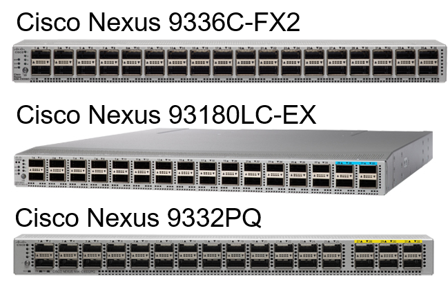
Cisco Nexus 9300 ACI Fixed Leaf Switches
Cisco ACI leaf spectrum includes:
- 40/100-GE switch examples:
- Cisco Nexus 9336C-FX2 (36x 40/100GE)
- Cisco Nexus 93180LC-EX (24x 40/50GE, 6x 40/100GE)
- Cisco Nexus 9332PQ (32x 40GE)
The Cisco Nexus 9336C-FX2 Switch is a 1RU switch that supports 7.2 Tbps of bandwidth and over 2.8 bpps.
The switch can be configured to work as 1/10/25/40/100-Gbps offering flexible options in a compact form factor. All ports support wire-rate MACsec encryption.
The Cisco Nexus 93180LC-EX Switch is the industry’s first 50-Gbps hardware capable 1RU switch that supports 3.6 Tbps of bandwidth and over 2.6 bpps
across up to 24 fixed 40/50-Gbps QSFP+ ports and 6 fixed 40/100G-Gbps QSFP28 ports.
While the switch consists of 32 ports of QSFP, ports numbered 26 and 28 are disabled and 25, 27, 29, 30, 31, and 32 can be configured as 40- and 100-Gbps ports. This switch is capable of supporting flexible port configurations.
The Cisco Nexus 9332PQ Switch has 32 x 40 Gbps Quad Small Form Factor Pluggable Plus (QSFP+) ports. All ports are line rate, delivering 2.56 Tbps of throughput in a 1-rack-unit (1RU) form factor.

Other leaf switch platforms include the following:
- EX Series:
- 93180YC-EX (48x 1/10/25GE, 6x 40/100GE)
- 93108TC-EX (48x 100M/1/10GE Copper, 6x 40/100GE)
- FX Series:
- 93180YC-FX (48x 1/10/25-Gbps, 6×40/100GE)
- 93108TC-FX (48x10G BASE-T, 6×40/100GE)
- 9348GC-FXP (48x 100M/1G BASE-T, 4×1/10/25GE)
- FX2 Series:
- 93240YC-FX2 (48x 1/10/25GE, 12x 40/100GE)
- GX Series:
- Cisco Nexus 93600CD-GX (28x 100GE, 8x 400GE)

Cisco ACI Leaf Generations
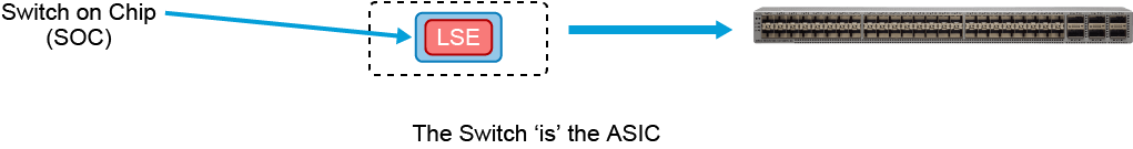
The Gen-1 Cisco Nexus 9300s are a combination of the Application Leaf Engine (ALE) and Network Forwarding Engine (NFE). The Gen-2 Cisco Nexus 9300-EX and -FX platform switches are built with the Cisco Cloud Scale ASIC Leaf Spine Engine (LSE).
The Cloud-Scale ASICs are manufactured using 16-nm technology, whereas merchant silicon ASICs are manufactured using 28-nm technology.
The 16-nm fabrication can place more transistors in the same size of the die as the one used for merchant silicon.
It has enabled Cisco to build a single switch-on-a-chip (SoC) ASIC that offers the following advantages:
- Higher bandwidth and greater port density at a lower price: Cisco Nexus 9300-EX and -FX switches offer multispeed 10- and 25-Gbps ports for the price of 10-Gbps ports, and 40- and 100-Gbps ports for the price of 40-Gbps ports. The switches also offer higher bandwidth and greater port density per rack unit, for a lower cost per port.
- Larger buffer size: Cisco Nexus 9300-EX and -FX switches have larger internal buffers (40 MB versus 16 MB) plus several enhanced queuing and traffic management features not found in most merchant silicon switches.
- Larger table size: Cisco Nexus 9300-EX and -FX switches support up to 256,000 MAC address entries in hardware and 256,000 IP host entries—much more than with merchant silicon-based switches.
- Deep visibility and telemetry information: Cisco Cloud Scale ASICs enable visibility into every packet and every flow at line rate with no negative impact on the CPU of Cisco Nexus 9300-EX and -FX switches.

Cisco 300-620 and 300-625 Exams: Practice Tests 2020
Testing your knowledge and pass your Cisco exam (300-620 and 300-625) in first attempt (Updated 2020)
Description
Welcome to the practice test for exam Cisco 300-620 and 300-625 Exams: Practice Tests 2020
Implementing Cisco Application Centric Infrastructure (300-620 DCACI)
This exam tests your knowledge of Cisco switches in ACI mode including:
- ACI Fabric Infrastructure
- ACI Packet Forwarding
- External Network Connectivity
- Integrations
- ACI Management
- ACI Anywhere
Implementing Cisco Storage Area Networking (300-625 DCSAN)
This exam tests your knowledge of Cisco MDS 9000 series switches, including:
- Deployment
- Implementation
- Management and monitoring
- Troubleshooting
This practice test will help you prepare for the real exam test environment with New Updated questions .
Introducing Cisco ACI Fabric Infrastructure and Basic Concepts
Cisco ACI Object Model
Instead of opening up a subset of the network functionality through programmatic interfaces, like previous generation software-defined networking solutions, the entire infrastructure is opened up for programmatic access.
This is achieved by providing access to Cisco ACI object model, the model that represents the complete configuration and runtime state of every single software and hardware component in the entire infrastructure.
Further, this object model is made available through standard REST interfaces, making it easier to access and manipulate the object model, and hence, the configuration and runtime state of the system.
At the top level, the Cisco ACI object model is based on promise theory which provides a scalable control architecture with autonomous objects responsible for implementing the desired state changes provided by the controller cluster.
This approach is more scalable than the traditional top-down management systems which require detailed knowledge of low-level configurations and the current state.
With promise theory, desired state changes are pushed down and objects implement the changes, returning false when required.
Beneath this high-level concept is the core of the Cisco ACI programmability, the object model. The model can be divided into two major parts, logical and physical. The Cisco ACI model provides comprehensive access to the underlying information model, providing policy abstraction, physical models, and debugging and implementation data.
The Cisco ACI northbound layer can be accessed over REST APIs, thus opening up the system for programmability with languages like Python.
Whereas the southbound APIs use OpFlex for devices that are enabled for Cisco ACI and for scripting tools for integrated third-party partner devices.
The logical model itself consists of objects, configuration, policies, and runtime state that can be manipulated and the attributes of those objects.
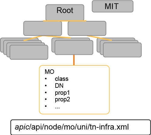
In the Cisco ACI framework, this model is known as the Management Information Tree, MIT. Each node in the MIT represents a managed object or a group of objects.
These objects are curated in a hierarchical way, creating logical object containers.
Object instances are referred to as managed objects, MOs. Every managed object in the system can be identified by a unique distinguished name, DN. This approach allows the object to be referred to globally.
Because of the hierarchical nature of the tree and the attribute system used to identify object classes, the tree can be queried in several ways for managed object information.
Queries can be performed on an object itself through its distinguished name on a class of objects, such as switch chassis or on a tree-level discovering all members of an object.
In this example, we have two chassis being queried at the tree level. Both queries return the referenced object and its child objects.
This approach is a useful tool for discovering the components of a larger system. Class level queries, on the other hand, return all the objects of a given class.
This approach is useful for discovering all the objects of a certain type available at MIT. In this example, the class used cards, which returns all the objects of type cards.
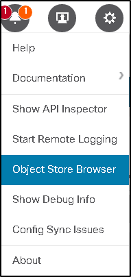
You can query or view the MIT in different ways– Object Store Browser, or Visore, browsing MIT in the shell directly, MoQuery, which is a direct CLI query to the database, RESTful APIs using Postman, icurl, which is a local REST client on the APIC and leaf, or you might use a software development kit such as Python.
Quick example if you want to use the Object Store Browser from the Help menu, which is what we also call Visore– this is a utility that is built into the Cisco APIC itself that allows you to easily browse MOs using an html browser.
All you need to do is just enter the class name in the class bar, and maybe you want to just filter specific objects to return certain objects instead of the overall class.
Then run the query, and you can just keep reading it and find out the different objects found in that specific class.
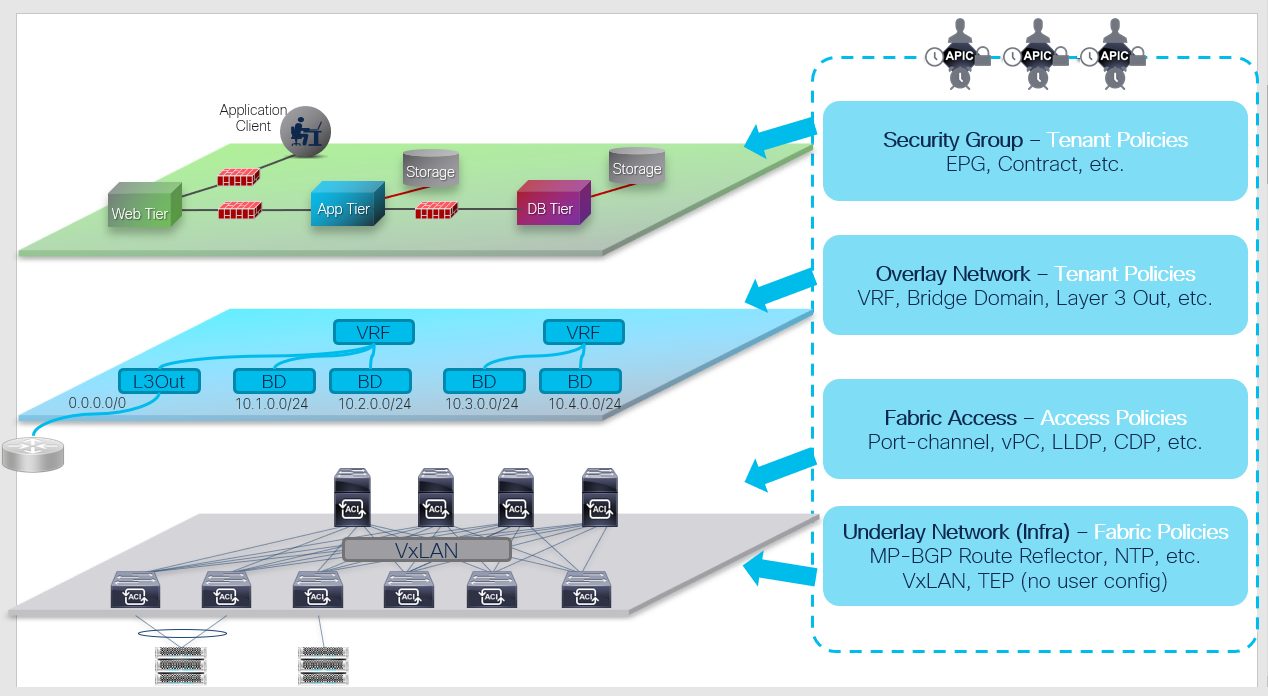
The Cisco ACI manages all the configurations as objects stored in management information tree (MIT) database. As an overview, policies can be categorized in 4 major groups, as shown in the figure above:
- Security Group (Security/Application Tenant Policies): This defines how ACI fabric should allow network communication between two devices. Example policies are endpoint groups (EPGs), contracts, etc.
- Overlay Network (Network Tenant Policies): This defines the overlay network that goes over the ACI fabric. These policies will be the logical topology of user networks and can be defined without worrying about the underlay. Example policies are VRF, bridge domain (BD), etc.
- Fabric Access (Access Policies): This defines how end hosts or external network devices are connected to ACI fabric by configuring port-channel, vPC, and other interface-level configurations.
- Underlay Network (Fabric Policies): This defines the VXLAN underlay built by ACI fabric along with infra Multiprotocol Border Gateway Protocol (MP-BGP) and other protocols to manage ACI switches such as NTP.
The details of each policy will be described in a later topic (Cisco ACI Access Policies). In this topic instead, it is explained what policies or objects are in the first place and how to check them in general. Although these may not make sense at first, the basic knowledge in here will be useful when you actually configure ACI Fabric and verify some configurations.
In the Cisco ACI, all objects are stored in a tree called MIT as mentioned before. And each object is called a managed object (MO).
All information including config, hardware component (such as leaf, fan), control plane status (such as OSPF), stats (such as interface stats), and some logs (faults, event, audit log) are stored as an object in MIT that can be easily processed in a programmatic way.
These objects are accessible through REST API and most of the operations in ACI is using the REST API in the background.
You can directly use the REST API to access the ACI Fabric data or can use GUI or NX-OS style CLI. But in the background, REST API is called.
Configuration is through REST API (or GUI, NX-OS style CLI that runs API in background).
The user configurations are called logical model objects and it’s translated into objects called concrete objects when passed down to switch nodes.
Then switch nodes apply the configuration to hardware based on the concrete objects.
Each object is represented by an ID called distinguished name (DN). Each distinguished name belongs to a class which is a type of object.
To check the object directly instead of using GUI or NX-OS style CLI, you can directly check distinguished name to get a specific object. Or you can check a particular class to get all objects of that type.
Obtaining the Distinguished Name from the GUI
In the GUI, the easiest way to get the distinguished name (DN) and class of an MO is to show debug information.
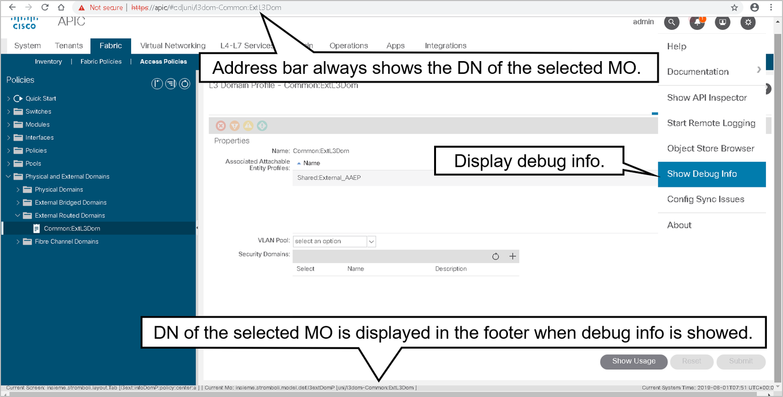
In the example, you can find out the Distinguished Name and the class of the managed object by observing the bottom of the GUI.
Obtaining the Disinguished Name from XML
You can also get an object distinguished name from XML. Simply select an object in GUI, right-click, and choose Save as. You can choose to save all properties of an object, or only configuration, scope, and export format.

You can obtain distinguished name and object attributes from XML.

Methods and Tools to Query the MIT
The MIT can be queried for all objects of a specific class or distinguished name, and then it can retrieve the children or complete subtree for the returned objects.
The data sets can also be filtered to return only information that is specific to your purpose.
A class-based query is useful when multiple objects information needs to be reviewed.
A class-based query combined with filtering can be a powerful tool to extract data from the MIT. As a simple example, a class-based query can be used to find all fabric nodes that are functioning as leaf, and extract their serial numbers, for a quick way to get a fabric inventory.
An object-based (distinguished-name-based) query returns zero or 1 matches, and the full distinguished name for an object must be provided for a match to be found.
You can query or view the MIT in different ways:
- Object Store Browser: https://apic_ip/visore.html or from Cisco APIC GUI
- Browsing MIT in shell: cd /mit/… or cd /aci
- Moquery: Direct CLI query to the database
- REST: Postman, curl GET and POST
- icurl (local REST client on apic/leaf)
- Python SDK
These two types of queries are supported:
- Class-level query: search the MIT for objects of a specific class
- Object-level query: search the MIT for a specific distinguished name
Regular expressions (regex) can be a powerful tool when used with the grep command to search through logs and information available in Cisco APIC.
Object Store Browser
Visore or Object Store Browser is a utility that is built into Cisco APIC and allows a user to easily browse MOs using an HTML browser.
The functionality is similar to what is used in the Cisco Integrated Management Controller (IMC).
The Object Store Browser utility uses the Cisco APIC XML API query methods to browse the MOs that are active in the Cisco APIC.
You cannot use the Object Store Browser utility to perform configuration operations.
The core principles of Object Store Browser are as follows:
- Managed Object browser in GUI
- Can be accessed in various ways:
- From Help and tools icon in APIC GUI.
- Right-click on any ACI object in the GUI.
- By connecting to https://apic_ip/visore.html
- Used to retrieve:
- All object of a certain class
- Certain DN object
- Review object properties
- Relations to parent and children objects
To query for a particular class, enter the class name in the Class or DN field and click Run Query.
Object Store Browser sends a configResolveClass method to Cisco APIC and the requested MO is displayed in a tabular format.
Use the less than (<) and greater than (>) buttons to retrieve the parent and child class of the displayed MO.
For example, clicking > sends a configResolveChildren method to Cisco APIC to query for the child of the MO. Clicking < sends a configResolveParent method to Cisco (IMC) to query for the parent of the MO.
To query for a particular DN, enter the DN in the Class or DN field and click Run Query. Object Store Browser sends a configResolveDn method to the Cisco APIC.
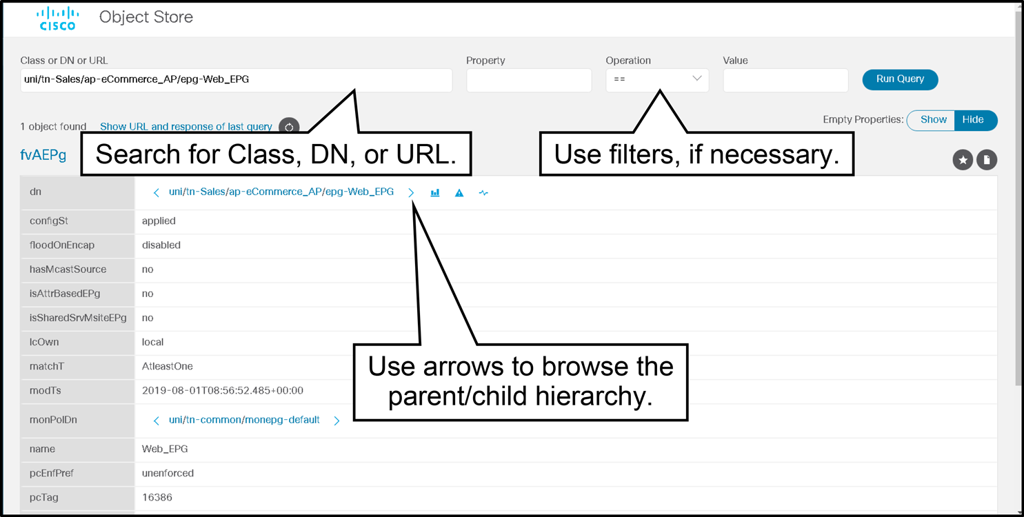
Moquery
Moquery is a CLI utility that allows querying of the MIT from the command line. It is also known as the command-line cousin to Object Store Browser.
The pros of Moquery are as follows:
- Easy to use
- Good to catch few objects
- Purely CLI based, no need of anything else
- Output very easy to read
- One line per parameter, easy to grep
Moquery Cons:
- No browsing capability (parent-child) like Object Store Browser
- Not as fast and efficient as a direct API call
Moquery help:
apic1# moquery -h
usage: Command line cousin to visore [-h] [-i HOST] [-p PORT] [-d DN]
                                     [-c KLASS] [-f FILTER] [-a ATTRS]
                                     [-o OUTPUT] [-u USER]
                                     [-x [OPTIONS [OPTIONS ...]]]
optional arguments:
  -h, --help            show this help message and exit
  -i HOST, --host HOST  Hostname or ip of apic
  -p PORT, --port PORT  REST server port
  -d DN, --dn DN        dn of the mo
  -c KLASS, --klass KLASS     comma seperated class names to query
  -f FILTER, --filter FILTER      property filter to accept/reject mos
  -o OUTPUT, --output OUTPUT   Display format (block, table, xml, json)
  -u USER, --user USER             User name
  -x [OPTIONS [OPTIONS ...]], --options [OPTIONS [OPTIONS ...]]
                        Extra options to the query
Syntax description:
--dnor–dspecifies a distinguished name (DN) for a managed object (MO)--klassor–cspecifies a class name for the query; you can enter multiple classes separated by commas--filteror–fspecifies a property on which to filter MOs.--optionsor–xspecifies query options. You can specify query options as supported by the REST API. You can add multiple options statements to the command.
Next, look at examples of using moquery command.
List all the EPGs in the fabric:
admin@apic1:~> moquery -c fvAEPg | grep dn
dn                   : uni/tn-infra/ap-access/epg-default
dn                   : uni/tn-infra/ap-ave-ctrl/epg-ave-ctrl
dn                   : uni/tn-Sales/ap-eCommerce_AP/epg-App_EPG
dn                   : uni/tn-Sales/ap-eCommerce_AP/epg-DB_EPG
dn                   : uni/tn-Sales/ap-eCommerce_AP/epg-Web_EPG
dn                   : uni/tn-Sales/ap-eCommerce_AP/epg-Backup_EPG
List the details of a specific DN:
admin@apic1:~> moquery -d uni/tn-Sales/ap-eCommerce_AP/epg-App_EPG
Total Objects shown: 1

# fv.AEPg
name                 : App_EPG
annotation           :
childAction          :
configIssues         :
configSt             : applied
descr                :
dn                   : uni/tn-Sales/ap-eCommerce_AP/epg-App_EPG
exceptionTag         :
extMngdBy            :
floodOnEncap         : disabled
fwdCtrl              :
hasMcastSource       : no
isAttrBasedEPg       : no
isSharedSrvMsiteEPg  : no
lcOwn                : local
matchT               : AtleastOne
modTs                : 2019-10-07T09:09:56.780+00:00
monPolDn             : uni/tn-common/monepg-default
nameAlias            :
pcEnfPref            : unenforced
pcTag                : 49154
prefGrMemb           : exclude
prio                 : unspecified
rn                   : epg-App_EPG
scope                : 2162688
shutdown             : no
status               :
triggerSt            : triggerable
txId                 : 7493989779947184498
uid                  : 15374
The -f option allows you to specify a filter. In the following example, you can see the result of querying all the DNs in which fault F0467 is present. You can use any property of an object of that class as a filter code. For faultInst, that property could be Severity, lc (life cycle), code and so on.

Moquery with filter:
admin@apic1:~> moquery -c faultInst -f 'fault.Inst.code == "F0467"' | egrep dn
dn               : topology/pod-1/node-101/local/svc-policyelem-id-0/uni/epp/rtd-[uni/tn-L3/out-BGP-Out/instP-epg-l3-bgp]/node-101/stpathatt-[eth1/8]/nwissues/fault-F0467
dn               : topology/pod-1/node-102/local/svc-policyelem-id-0/uni/epp/fv-[uni/tn-DC/ap-App/epg-EPG3]/node-102/stpathatt-[eth1/33]/nwissues/fault-F0467
dn               : topology/pod-1/node-104/local/svc-policyelem-id-0/uni/epp/fv-[uni/tn-infra/ap-access/epg-default]/node-104/attEntitypathatt-[VMM]/rsstPathAtt-[sys/conng/path-[eth1/46]]/nwissues/fault-F0467
admin@apic1:~>
Next, there are examples of querying the encap (wire) VLAN ID.
List all VLAN use anywhere as encap in the fabric:
admin@apic1:~>  moquery -c vlanCktEp | grep '^encap' | sort -u
encap                    : vlan-10
encap                    : vlan-112
encap                    : vlan-120
Where do you use vlan-120?
admin@apic1:~>  moquery -c fvIfConn | egrep "dn.*vlan-120]"
dn          : uni/epp/fv-[uni/tn-DC/ap-App/epg-EPG1]/node-102/stpathatt-[n7k2-vpc]/conndef/conn-[vlan-120]-[0.0.0.0]
dn          : uni/epp/fv-[uni/tn-DC/ap-App/epg-EPG1]/node-101/stpathatt-[n7k2-vpc]/conndef/conn-[vlan-120]-[0.0.0.0]
dn          : uni/epp/fv-[uni/tn-DC/ap-App/epg-EPG1]/node-101/stpathatt-[eth1/33]/conndef/conn-[vlan-120]-[0.0.0.0]
admin@apic1:~>
You can see that vlan-120 is used by EPG : EPG1 in tn-DC on node 101 to 102. This is fvStPathAtt (Static Path) going, for example, on a vPC on 101-102 called n7k2-vpc and also on 1/33 on node 101.
Faults, Event Record, and Audit Log
you want to monitor your Cisco ACI fabric. Well, monitoring has never been easier.
Because in Cisco ACI, we have several objects that are created for us which assist in the monitoring and troubleshooting aspects. Faults, events, and audit logs.
Faults first. As the name implies, and to explain it in just three words, what is wrong? Yeah.
This is what faults is all about. All technical issues that might arise due to hardware failure, APIC clustering problems, and– wait for it– bad configuration.
Well, in the standalone NX OS mode, how many times have you trunked a VLAN under an interface and originally forgot to create the VLAN that you wanted to trunk? Did the NX OS ever warn you that something is missing? Never.
Well, with faults in Cisco ACI, you will be getting a fault code, F0467, which notifies you about invalid VLAN.
Once that VLAN has been created and defined correctly, the fault would disappear. A very simple example that shows how fault is powerful and helpful.
If you navigate to System then Faults, you can see a list of all the faults in the system. And if you Double-Click on one of them, you can see the full properties.
And one of the beautiful things about faults is that it does not only display the problem, but it also shows you the troubleshooting suggestion. As seen here, the recommended action is to replace the power supply unit that has failed.
Then, we talk about events. An event describes a certain condition that happened during a point of time– good or bad, positive or negative.
For example, a link went from down to up or vise versa. And we also have the audit log, which would track all the configuration changes that keep happening in the APIC to actually keep an eye on the administrators.
What have they configured, and when did that happen?
Another very helpful policy model in the ACI fabric is the health score. It enables you to isolate performance issues by drilling down through the network order to isolate faults to specific managed objects.
It grades those managed objects based on a score level from 0 to 100%.
The higher the score, the better the performance. Maximum performance is 100%. High is 80%. Medium is 50%. Low is 20%.
And 0% means the object is completely down. These impact levels between objects are user configurable.
The APIC supports the following health score types. First, system, which summarizes the health of the entire network. Then, we have the aggregation of health scores for a pod, which is a group of spine and leaf switches.
And finally, the tenant, which summarizes the health of a tenant and the tenant’s applications.
Based on object status or changes, the Cisco APIC generates the following objects for logging purpose:
- Faults: for issues in the fabric (such as an issue in configuration or a fan failure on a node)
- Events: for events in the fabric (similar to `show logging log` in standalone NX-OS)
- Audit Logs: for configuration changes in the fabric (similar to `show accounting log` in standalone NX-OS)
These logging objects are created against a certain object (could be a configuration object or an object representing a hardware component etc) and can be checked via REST API, GUI or CLI. For details about each logging object, please refer to the following sections.
These can also be exported to the existing network monitoring system in a respective format such as Syslog, SNMP trap, Cisco Call Home message.
On top of these three logging objects, the Cisco APIC can also display an error message in the GUI and the CLI to prevent some of unsupported operations or to display a warning.
Faults in the Cisco ACI
Fault is your friend in ACI. Whenever you are performing a configuration, please always check the fault to ensure ACI fabric doesn’t detect any mis- or bad configuration.
For example as a benefit of Faults, in a standalone NX-OS, there are no logs or warnings when VLAN 10 is trunked on an interface without creating VLAN 10. You just need to know about it.
In a similar situation in ACI, however, a fault F0467 is raised and it notifies you about Invalid VLAN.
Once the VLAN 10 is created and defined correctly, the fault disappears. Since ACI introduced objects model configuration which may be different from normal switches configuration procedure, Faults are a very powerful tool to make sure the configuration is correct.
On top of the configurations, it’s also raised against any abnormality in the fabric such as hardware failure, APIC clustering issues etc. Hence, monitoring of faults is the primary key to use and operate ACI.
In normal switches, similar functionality is achieved with system message, which is Events in ACI that includes both positive and negative events.
However, ACI Faults is only for issues that need to be addressed on top of the bad configuration detection, which is the reason why Faults is the first thing to check whenever something is not working.
Faults have two types (class) of objects:
- fault:Inst: When a fault condition is met on an object, a faultInst object is created under the object that experienced the fault condition.
- fault:Delegate: Many objects are used internally by the system and are not presented conspicuously in the APIC GUI.
- In order to improve the visibility of a fault that might otherwise go unnoticed, for some faults a corresponding faultDelegate object is created and attached to an object that has higher visibility in the APIC. A fault delegate object is an identical copy of the original faultInst object.
In APIC GUI, most of the components have a tab for Faults that shows all fault objects related to the component. Or users can use REST API to pull required fault objects.
The following example shows how to use APIC GUI to find out information about a fault that was raised.
If you navigate to System > Faults you can see a list of all the faults in the system. If you double-click on one of them you can see the Fault properties.
You can see in the following screen capture that the Power supply on Node-1 has failed.
To see the explanation about the fault and the recommended action to remediate that fault click on the Troubleshooting tab.
As seen in the following example, the recommended action is to replace the power supply unit that is failed.
You can also see the audit log for the specific time before the fault.

ACI Faults have a state called life cycle.
When a new fault is created or its life cycle changes, a faultRecord object is created to log the transition of faults.
This is very useful to analyze the status of the fabric when an issue was present in the past.
Fault Record objects are purged only when the maximum capacity is reached, and space is needed for new faultRecords.
Note
The default for the clearing interval is 120 seconds, the retention interval is 3600 seconds, and the soaking interval is 120 seconds.
To view a summary of fault statistics for the overall system, login to the APIC GUI and click System in the menu bar, followed by the Faults in the submenu bar.
In addition, you can observe the fault counts by domain and fault counts by type (grouped by severity levels) by clicking on the Dashboard.
You can acknowledge faults, so you can quickly distinguish between faults that are new and faults that you have already seen.
When you acknowledge a fault in the retaining state, the fault will be deleted immediately (without waiting for expiration or retention timer). However, acknowledging a fault in any other state has no effect other than setting the property ACK to yes.
Events and Audit Logs
An event is a specific condition that occurs at a certain point in time (for example, “link went from down to up”), which might be of interest to the user.
The following are the objects for events and audit logs:
- eventRecord: an object for events
- aaaModLR: an object for configuration changes (audit logs)
- aaaSessionLR: an object for logins and logouts (audit logs)
Events and Audit Logs are similar to an entry in a log file. After the system creates an event, the event is never modified or cleared.
An event MO such as eventRecord or aaaModLR is deleted by the rotation of the event log (its maximum value is specified in the retention policy), as newer events are added, and log space is needed.
To show eventRecord in APIC GUI, navigate to System > Events.
To show the audit logs in APIC GUI, navigate to System > Audit logs.
Health Scores
The Cisco APIC uses health scores to indicate the status of the ACI fabric. This is a number to be monitored for health check.

A health score is a number between 0 and 100 that is derived from a predetermined weighting system.
Therefore, Cisco APIC uses a single consolidated health score that shows the status of all the objects including links, devices, their relationships, the real-time status of their utilization, and a quick at-a-glance assessment of the status of the entire system or any subset of the system.
When there are faults raised by any object that the Cisco APIC manages, the weighting system degrades the health of that object, and also the health of any object in the model that depends on that object with a degraded health score.
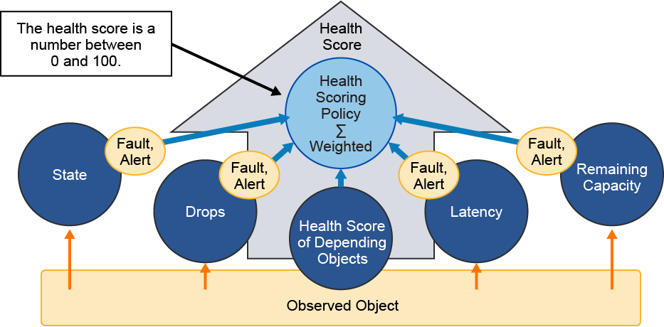
Most of MOs have an associated health score, which can be found from the Dashboard or Policy tabs of the object from the APIC GUI.
To check the overall fabric health, login to the GUI and click System in the menu bar, followed by the Dashboard. You can view the following information:
- The system health, which provides a health graph depicting the health score of the system over a certain time period.
- Nodes with health less than 99.
- Tenants with health less than 99.
Use the health graph to detect any system issues over time. If the system is stable, the graph is a constant. If the system is not stable, the graph fluctuates.
Cisco ACI Fabric Discovery
This is ACI fabric discovery.
So you’re in the kitchen trying to cook your favorite dish, pizza. You have the ingredients, but you don’t know how to mix them up.

This is what we’re trying to do in this lesson, not to teach you how to cook pizza, but how to bring up the fabric, how to discover the fact, how does the APIC, the different switches, the spines, the leaf, try to talk and communicate together in order for the fabric to be formed?
So we’re going to be talking about the prerequisites and then the kind of messages which are being sent between these different devices. And then we’re going to try to do minimal configuration on the APIC devices then verify in the end each and everything that we did to make sure that the discovery has been successful from the CLI and from the GUI. So let’s get going.
First, prerequisites, what do we have here? And what have we already learned from before? And what do we need to make sure about?
Number one, we want to make sure that we’ve already defined that topology that we’ve been talking about, the spine and leaf topology.
So we have a bunch of spine switches and some leaf switches. How do we connect them together, real quick?
Spines to leaves and leaves to spines only, you do not connect leaves to leaves or spine to spines.
You also have your APICs.
How many APICs do we have? Let’s say for this example, we have three APICs for redundancy. And you know that we have to cluster them together, the version of the firmware and the switch nodes as well needs to be the same. You don’t want to have inconsistent software running on all these devices.
And one more thing, that is the initial configuration script that you need to be configuring your APIC with.
So what kind of questions do you need to answer? And that’s not going to be extensive kind of configuration. It’s just like in form of a dialog question and answer, easy and simple.
So the initialization process, we have the fabric. We have the bunch of devices that we all know about, the spines, the leafs, and the APICs. And for making a good clear example, we have a couple of devices or servers that we can see here in this diagram, a virtual machine or a physical bare metal switch, or physical bare metal server.
So we’re going to connect these devices together. Again, remember the point, spinal leaf. So how do we connect these? I guess you remember, spines to leafs and leafs to spines only.
And then we connect the APICs to leafs only. So I want to make sure that each APIC is connected to a couple of leafs for redundancy.
And they should be different. I would say it’s better if they’re different so that you have optimum redundancy.
What is going to be the very first step? Well, you might have guessed it. I need to configure my APIC because this is the central point of controlling everything. You’re not going to be hopping to any of the devices at this point.
You need to configure APIC number one. Let’s consider that the first APIC, or APIC number one is the one on the very left-hand side.
So you’re about to form a cluster. But that doesn’t happen until you do the configuration.
So you have the initial setup script that we’re going to talk about in a few seconds. That’s the moment where after you finish the setup script, some protocols are going to be running between the different switches and the APIC.
So we’re talking here about LLDP. We’re talking about DSCP and IS-IS routing protocol.
Remember those from the previous videos. This is what’s going to happen. So we need to know where exactly in this diagram will these protocols be present.
So right now, you’re APIC is trying to discover the first switch it is connected to, in this diagram here, the first leaf switch. It’s going to send some kind of LLDP messages. Link Level Discovery Protocol will try to inform the APIC whether that switch is there or not. And then once this happens, and they know about the existence of one another.
Hey, Mr. APIC– who’s talking now? It’s the leaf.
Hey, Mr. APIC, you know what? I want an IP address for myself. And since you’re the controller here, so why don’t you just lease one of your IPs to me?
So that’s what’s going to happen. Hey, Mr. Leaf number 1, here’s your IP address. And that was a DSCP message. What happens next is like, who is after you. Mr. Leaf number 1, I think that you’re connected to some other switches in this diagram or in this topology.
So why don’t you help me– who’s talking? The APIC. Why don’t you help me discover the rest of the fabric.
And what I mean by the rest of the fabric here, each and every switch in this diagram.
So leaf number 1 is still talking here.
Hey, Mr. Spine, you know what? We have a friend of ours over here who’s trying to take over.
And I just want to introduce you to our APIC. So why don’t you just give me some information about yourself, so an LLDP message again.
But this time from where to where? From the first leaf switch to the first spine switch.
We’re talking here about these numbers, which are in our diagram.
So let’s say leaf 101 is trying to talk to spine 201. They discovered one another so leaf 101 is going to report this back to the APIC.
Hey, Mr. APIC, we’ve got a new member here. Do you want to just help in giving him an IP address just like you gave me one?
So that’s going to happen again repeatedly. But this time the leaf is going to relay that DSCP message to the topmost spine.
Let’s repeat this thing over and over again until all those switches are being discovered.
So step number 4 here is that all the switches are contributing in the discovery process with the LLDP and the DSCP messages which are being relayed back and forth through the APIC so that each and every device has an IP.
What is happening behind the scene after that, after all the devices now had their IP addresses.
And just for your information, these IP addresses that were leased, they are being used in the overlay TEP IP addresses, Tunnel and Point IP addresses.
So later we need to be friends. Who? We exactly need to be friends, the leafs and the spines.
We need to discover one another in such a way that we can later on communicate.
Not just over the discovery phase but in order to send traffic later on. So we need to have some kind of routing vertical.
And we know and remember that the ACI fabric is routed, is a routed fabric.
It’s based on Layer 3. So again, do you remember that thing, which routing protocol? Yep, you might have got it right, IS-IS routing protocol.
That is also being automated for you. That is also being pushed automatically by the APIC to each and every device in the fabric.
So that now in that step 5, they are all IS-IS neighbors. Quite good.
So what is missing now? The last step is for the cluster to be formed. Because we have a pick number 2, and we have a pick number 3 as well.
So we want to make sure that everything is consistent, and hey, 2 and 3, you’re friends of mine. Who’s talking? APIC number 1. 2 and 3, you’re friends of mine. You’re here to just make it 1. You know, we have to work together.
So you want to make sure that you’re not just redoing whatever I’ve just done, OK? So you will discover the rest of the fabric.
You will just talk to the other devices but do not pass any configuration to them. And make sure that whatever they are telling you about is what you store in your data. How are you going to be making sure about that, Mr. APIC 2 and 3? You are going to be checking this using something called the appliance vector, OK.
So now that everything is being discovered, let’s see how we can verify these things. We are going to verify these things again on two levels, from the CLI level if you wish and also from the GUI level. So starting with the CLI, here is this stage, which I’m taking you one step backward where actually, this is the point where you were configuring the APIC itself.
Remember that setup script, remember that step number 1, that’s actually the detail of step number 1– what kind of questions you will be asked and what kind of answers you should give there. So you can see here, it’s fabric name, fabric ID, number of active controllers, let’s walk you through these different questions.
So the fabric name is– if you just want to give a name for your entire fabric, the ACI fabric, just any name.
If you just click Enter or hit Enter, it’s going to be just whatever value that is here in between brackets. So you can see your ACI fabric one being the name.
And then the next question is fabric ID doing a number in case you have multiple fabrics. Yes, that’s possible. Just go from one, two, three, whatever. Whatever number you’re comfortable with.
And the number of active controllers in this case, in this scenario of ours, we have three, OK.
So you’re going to go for three POD IDs in case your APICs are being distributed across different physical locations. So you want to tell the APIC which POD number you’re located in. That’s one of the questions there.
And then standby controller, which is an option in case you want to have one more controller acting as a standby one in case one of the three dies.
So this is an option. If you want to go for it, it’s fine. At this moment, we’re not configuring it. APIC X as of this version of the APIC version 4.1, we’re not going to be using it. So I would go for a default no.
Controller ID, how many controllers? We have three. So give them a number, each and every one. And then you might need to name these controllers if you wish.
We’re going to have an IP address pool that will be used for the DSCP allocation. Remember that thing when we were talking about leasing IP address, leasing from Mr. APIC? You’re leasing from a pool. This is the pool that you’re trying to lease from, the TEP addresses.
So by default, you can see here it’s a 10-000-16. If you want to change that and have your own pool, that’s completely your choice. We are still continuing with this, a big list of questions. But again, you don’t need to worry about it. It’s easy and simple.
We have the VLAN ID which is the fabric infrastructure, VLAN that will be used within the fabric.
Do you see those messages that we were talking about?
They should be in a certain VLAN.
What is that VLAN number? Just choose any number that you want. And then the group IP outer which is a default feature that you might need to use.
If you just click Enter, it’s going to just choose this multicast IP address for the GIPO.
The last few things over here in this slide that you need to just worry about is the IP address, the management IP, the out-of-band management.
So later on if you want to manage your APIC devices, what IP addresses do you want to give them?
Well, try this here and at the default gateway if you wish. If you don’t, then just go for none.

And finally, you want to make it secure. So a password is always good. I’m going to create your password as well.
Verify, all right, so let’s see what happened behind the scenes. If you want to do the CLI style, that’s possible.
If you don’t want to do it, fine. We can still do it from the GUI as well.
But I’m a CLI geek myself. So I want to go for in any of the APICs, any of the three.
And then I’m going to hit ACI diag, av read, which is a command that will just give you all the information about that appliance vector that we were talking about which we’ll try to compare the different configurations that were pushed across the different APICs and the discovery that happens.
So you can see here in this first screen that we are at APIC number 1. So you are the local appliance. And this is your IP address.
Hey, where did you get this IP address from? I allocated it to myself.
If I’m the owner of the pool, remember that TEP pool? If I’m the owner of the pool, I would first start by allocating an IP for myself, for the fabric communication.
Make no mistake about it, we’ve talked about two different kinds of IPs, the OOB IP address, which you configured by yourself, the Out-Of-Band management for you, Mr. Network administrator, to be able to access the APIC. That’s one thing.
And the IP address that the APIC will use to communicate with the rest of the devices and let the devices communicate amongst themselves.
That’s the TEP pool and the TEP IP address. And you can see this very clear over here. Some hardware information also is listed in this output such as the CHASSIS_ID, the MAC address, all this different information that will tell you that this is the current APIC.
And then the output, still it’s a big screen, so the output.
More information about the second appliance and the third appliance, which is going to be pretty much similar information since they’re using the same firmware version.
So you can see here appliance number 2 and 3 as well.
Last but not least, I want to just see that from my GUI. Before just verifying that from the GUI there is a tiny little piece of configuration that you need to perform before verifying, which is registering those switches in the graphical user interface.
So if you notice here, we are in the fabric. And from the fabric in the inventory to be specific, you have the list of devices that are unknown at this stage.
It’s one. Or depending on how many devices that you have in there that are not yet discovered.
And I’m not saying, not yet discovered. But I’m trying to say here that you need to input some minimal configuration in there to let the APIC initiate the process of discovery.
Hey, I’m not going to discover it against your will, Mr. Administrator. So you need to tell me when to start the discovery, OK?
So this is the moment where you’re actually telling the APIC, hey, go and discover those devices.
So what are you going to be doing there? Specifying a node ID and a name, a role, and a POD ID, these different things that you need to give.
So once you add these different parameters in your GUI, this is where all the six steps that we’ve talked about will happen.
And then, it’s the moment I’ve been waiting for. You see, I’ve just discovered my leaves, my spines, regardless of the numbers here because they’re not matching my diagram.
So you can see one spine and two leaves. But actually, we had more than this in the diagram. So don’t worry about this. The bottom line here is you finally discovered your devices, and you can verify this from my screen.
I’m also going to verify my APICs. You said that we formed a cluster, so we’re going to see that. It’s going to be here but in a different TEP.
So you’re now in the system under the dashboard.
And this is like a summary dashboard or summary screen where you can see all those physical infrastructures that you’ve already discovered and created.
So you can see at the left-hand side here, the different leafs and spines that you’ve already discovered, and the cluster at the bottom, the cluster of these three different APICs that you just discovered.
With this, now you’ve learned how to make pizza, well, discover the fabric.
Cisco ACI fabric uses Link Layer Discovery Protocol (LLDP)- and DHCP-based fabric discovery to automatically discover the fabric switch nodes and to assign the infrastructure TEP addresses.
Before this automated process, some prerequisites need to be prepared.

Cisco ACI Fabric discovery prerequisites include:
- Initial cabling of the Cisco ACI fabric
- Initial setup script dialog to be completed on Cisco APIC nodes
- The same version of firmware on Cisco APIC nodes and switches
Initial cabling of the Cisco ACI fabric is very important, and the following requirements must be adhered to:
- Leaf switches can only be connected to spine switches. Leaf switches cannot be interconnected to each other, even when the leaf switches will be configured as virtual Port Channel (vPC) peer devices.
- Spine switches can only be connected to leaf switches. Spine switches cannot be interconnected to each other.
- A Cisco APIC must be attached to a leaf. Cisco APICs should be dual-homed (connected to two different leaf switches) for redundancy.
Setting Up Cisco APIC 300-620 DCACI
When setting up Cisco APIC for the first time:
- Use console and answer initial Cisco APIC setup script dialog questions
- After the initial setup, access the GUI via https://mgmt_ip-address
Cluster configuration ...
  Enter the fabric name [ACI Fabric1]:
  Enter the fabric ID (1-128) [1]:
  Enter the number of active controllers in the fabric (1-9) [3]:
  Enter the POD ID (1-254) [1]:
  Is this a standby controller? [NO]:
  Is this an APIC-X? [NO]:
  Enter the controller ID (1-3) [1]:
  Enter the controller name [apic1]:
  Enter address pool for TEP addresses [10.0.0.0/16]:
Note: The infra VLAN ID should not be used elsewhere in your environment
  and should not overlap with any other reserved VLANs on other platforms.
  Enter the VLAN ID for infra network (2-4094):
  Enter address pool for BD multicast addresses (GIPO) [225.0.0.0/15]:

Out-of-band management configuration ...
  Enable IPv6 for Out of Band Mgmt Interface? [N]:
  Enter the IPv4 address [192.168.10.1/24]:
  Enter the IPv4 address of the default gateway [None]:
  Enter the interface speed/duplex mode [auto]:

admin user configuration...
  Enable strong passwords? [Y]:
  Enter the password for admin:

  Reenter the password for admin:
When you set up the Cisco APIC for the first time, you will need to configure these parameters:
- Fabric name, fabric ID, number of active controllers, controller ID, and controller name: First, you must enter the fabric name, fabric ID, number of active controllers (default is 3, it can also be increased or decreased later), controller ID (which is a unique ID number for the Cisco APIC instance: 1, 2, or 3), and the controller name. Controller name and ID have to be unique among the different APICs in the cluster.
- POD ID: The pod ID to which this APIC is connected to. If it is your first APIC or if you don’t have more than a single pod installed, the ID will always be 1. If you allocated additional APICs across multiple pods, assign the appropriate pod ID where it is connected.
- Standby controller: Beyond your active controllers (typically 3) you can designate additional APICs as standby. If you have an APIC failure, you can promote a standby to assume the identity of the failed APIC.
- APIC-X: This option is beta for ACI Service Engine. Please always use the default “NO” and do not use.
- Address pool for TEP addresses: Enter the address pool for TEP addresses. The default IP address pool for TEP tunnel endpoint addresses is 10.0.0.0/16. This value is for the infrastructure VRF used for internal fabric communication. This subnet will not be exposed to your legacy network unless you are deploying the Cisco AVS/AVE. Regardless, the recommendation is to assign an unused subnet of size between and /16 and /21 subnet. The size of the subnet used will impact the scale of your pod. Most customers allocate an unused /16. This value cannot be changed once configured. Modifying this value requires a wipe of the fabric.
- VLAN ID for infra network: Enter the VLAN ID for the infrastructure network. This infrastructure VLAN is an important item and serves for inter-TEP and APIC-to-switch communication including virtual switches. Reserve this VLAN for APIC use only. VLAN ID must not be used elsewhere in your environment and must not overlap with any other reserved VLANs on other platforms. Though this VLAN is used for fabric communication, there are certain instances where this VLAN ID may need to be extended outside of the fabric such as the deployment of the Cisco AVS/AVE. This value cannot be changed once configured. Modifying this value requires a wipe of the fabric.

- BD Multicast Pool (GIPO): Used for internal connectivity. It’s recommended leaving this as the default or assigning a unique range not used elsewhere in your infrastructure. This value cannot be changed once configured. Modifying this value requires a wipe of the fabric.
- Configuring OOB management:
- Out-of-band management IP address: Enter the IP address for the OOB management, which is the IP address that you use to access the Cisco APIC through the GUI, CLI, or API.
- Default gateway IP address: Enter the IP address of the default gateway for communication to external networks using out-of-band management from APIC.
- Admin password: Set the password. The password of the system administrator must be at least 8 characters with one special character. This password is configured only on APIC 1 and will be synced to all other APICs and switches once other APICs join the cluster and switches are registered.
Once the Setup Dialogue has been completed, it will allow you to review your entries before submitting them.
After applying the configuration, allow the APIC 4-5 mins to fully bring all services online and initialize the REST login services before attempting to log in through a web browser.
You can access the Cisco APIC GUI via https://mgmt_ip-address using the out-of-band management IP address that you have configured during the initial setup.
When the login screen appears, log in as admin using the password that you have configured during the initial setup.
Note
This is regarding the first APIC 1. APIC 2, 3 etc.
will have fewer parameters in the Setup Dialogue because some parameters such as passwords are synced from APIC 1. APIC 2, 3, etc.
will be discovered and join the APIC cluster automatically once the infra TEP reachability between each APIC is established via leaf and spine switches.
Cisco ACI Fabric Discovery Process: The First Leaf 300-620 DCACI
The leaf switch that is directly connected to the Cisco APIC is discovered in the first stage of the fabric discovery process.
In the following figure, you can see the steps in this stage of the discovery process.
First, Cisco APIC uses LLDP neighbor discovery to discover a switch.
After a successful discovery, the switch sends a request for an IP address via DHCP.
If the APIC registers the discovered switch by giving the node ID and name, APIC then allocates an address from the DHCP pool, which is essentially the Address Pool for TEP address from the initial setup script dialogue.
The switch uses this address as a TEP IP address.
The assigned TEP IP will automatically show up in the Fabric > Inventory > Fabric Membership display in APIC GUI or you can verify the allocated address from APIC shell by using the acidiag fnvread command or the show switch command and by pinging the switch TEP or the switch node name from the Cisco APIC.
The switch node name is automatically resolved to the TEP address. This ping will go through the bond0 interface on APIC.
Once the TEP IP is assigned correctly on the switch, Cisco APIC initiates the encrypted TCP session with the switch to install policies to the switch and retrieve object information from the switch.
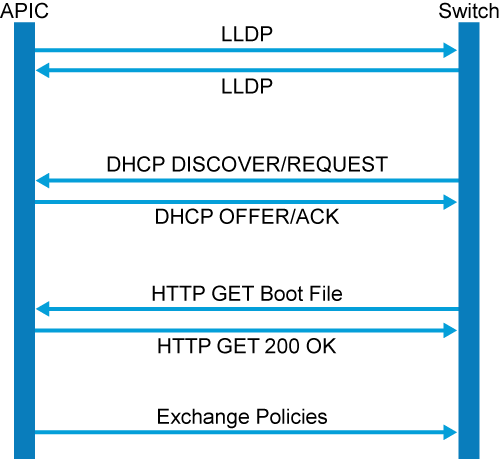
In summary, the initial steps of the discovery process are:
- LLDP neighbor discovery
- Users register the discovered node on Cisco APIC
- Cisco APIC assigns TEP address to the switch via DHCP
- Exchange policies (configuration from Cisco APIC to switch, inventory and other information from the switch to Cisco APIC, etc.)
Communication between the various nodes and processes in the Cisco ACI Fabric uses IFM, and IFM uses Secure Sockets Layer (SSL)-encrypted TCP communication.
Each Cisco APIC and fabric node has 1024-bit SSL keys that are embedded in secure storage. The SSL certificates are signed by Cisco Manufacturing Certificate Authority.
Note 300-620 DCACI
Once a switch is discovered in the Cisco ACI fabric discovery process, it is called a node.
In the discovery process, a fabric node is considered active when the Cisco APIC and the node can exchange heartbeats through the infra TEP.
Cisco ACI Fabric Discovery and Initialization Process: Leaf and Spine Switches
The Cisco ACI fabric is brought up in a cascading manner, starting with the leaf nodes that are directly attached to the Cisco APIC.
The LLDP and the control-plane IS-IS convergence occur in parallel from the first leaf to the spine switches, then to the rest of leaf switches.
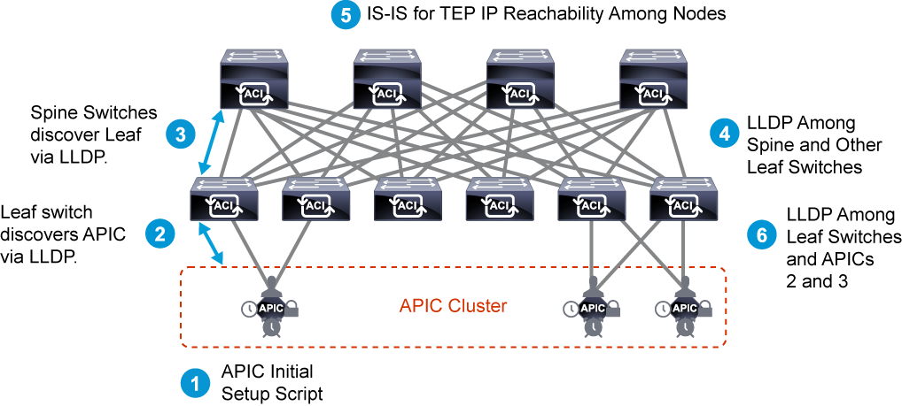
The following steps relate to the figure:
- Initial setup script dialogue on APICs: The parameters including infra VLAN are configured and used to build the ACI fabric.
- LLDP and DHCP between the first leaf and APIC: The first leaf discovers the infra VLAN via LLDP from APIC 1 and starts sending DHCP discover on it for TEP IP. APIC 1 also discovers the first leaf via LLDP.
- You register the discovered leaf by providing node ID and name. After the registration, APIC 1 starts responding to DHCP and assigns a TEP IP to the leaf. At this point, TCP session is established between the first leaf and APIC 1 via TEP IP for policy exchange. Other APICs have yet to join the cluster and cannot register and assign a TEP IP to switch nodes.
- LLDP and DHCP between the first leaf and spine switches: Spine switches discover the first leaf via LLDP and start sending DHCP discovers to the leaf. The leaf relays the DHCP discovers to APICs (in this case, there is only one APIC yet).
- The first leaf also discovers unregistered spine switches via LLDP and report them to APICs via the TCP session (in this case, there is only one APIC yet). Now, you can register all spine switches by providing node ID and name. After the registration, APIC 1 starts responding to DHCP for the spine switches and assigns TEP IPs to them.
- TCP sessions are established between each spine and APIC 1 via TEP IP as well.
- LLDP and DHCP between spine switches and the rest of leaf switches: The other leaf switches discover spine switches via LLDP and start sending DHCP discovers to the spine switches.
- The spine switches relay the DHCP discovers to APICs (in this case, there is only one APIC yet).
- The spine switches also discover unregistered leaf switches via LLDP and report them to APICs via TCP session (again, there is only one APIC yet).
- Then, you register the rest of leaf switches by providing node ID and name. After the registration, APIC 1 starts responding to DHCP for the leaf switches and assigns TEP IPs to them. TCP sessions are established between each leaf and APIC 1 via TEP IP as well.
- IS-IS for TEP IP reachability between each node: IS-IS is being dynamically and automatically formed between each node when the node is registered and policy exchange between APIC starts by downloading the configuration from APIC.
- This means it technically takes place during steps 3 and 4. This is not only for TEP IP reachability between switches but also for APICs to talk to switch nodes that are not directly connected to them.
- LLDP exchange between leaf switches and APIC 2 and 3: APIC 2 and 3 are discovered by directly attached leaf switches via LLDP. At this point, some of the initial setup parameters of APIC 1 is stored on all switch nodes in a form of Appliance Vector (AV). If there is no inconsistency between AV on the leaf and data in LLDP from APIC 2 and 3, the leaf switches will report them to APIC 1.
- Then, communications between each APIC begin and the APIC cluster is formed.
Note
You can also pre-configure the nodes based on serial number and have them being auto discovered when they are plugged in.
Cisco APIC Cluster Discovery Process
As partially mentioned above, APICs communicate with each other through the infra network formed by leaf and spine switches.
Hence, not only the APICs but also each switch node needs to know about some of APIC clustering information.
The information is stored in the form of AV. The important information stored in AV is the followings:
- Information of the entire fabric
- Fabric Name
- TEP Address Range
- APIC Cluster Size
- Information of each APIC
- APIC ID
- APIC TEP IP
- APIC Universally Unique ID (UUID) or chassis ID
This prevents invalid APIC to join the ACI Fabric. For example, if APIC 2 was replaced unintentionally without proper software awareness, switch nodes will detect mismatch in APIC ID and APIC UUID and block the new and possibly malicious APIC to join the fabric.
The following is the detailed steps for APIC Clustering Process:
- Switches are discovered and registered via APIC 1. All switches are updated with the latest AV with APIC 1 data in it.
- A new APIC (APIC 2) is connected to a leaf. The leaf checks some universal information such as Fabric Name since there is no entry about APIC 2 in AV at this point.
- If there is no inconsistency, it will report APIC 2 to APIC 1. If AV has an entry for APIC 2, it will check the UUID and ID mapping in the AV and LLDP TLV from the new APIC 2.
- APIC 1 and APIC 2 start communication and form a cluster. At this point, switches are aware of new APIC’s TEP IP via IS-IS from the leaf directly attached to the new APIC.
- Database sync is performed between APICs at this stage and each APIC will become Fully-Fit status once it’s fully synchronized.
- Repeat Steps 2 and 3 for APIC 3.
The AV on each node (both switches and APICs) can be checked via acidiag avread command:
admin@apic1:~> acidiag avread
Local appliance ID=1 ADDRESS=10.0.0.1 TEP ADDRESS=10.0.0.0/16 ROUTABLE IP ADDRESS=0.0.0.0 CHASSIS_ID=65b3e3d2-acb6-11e9-b3dd-f3bf116a1fd1
Cluster of 3 lm(t):3(zeroTime) appliances (out of targeted 3 lm(t):3(2019-07-22T19:28:40.965+00:00)) with FABRIC_DOMAIN name=Fabric1 set to version=4.1(1l) lm(t):1(2019-07-22T19:28:42.670+00:00); discoveryMode=PERMISSIVE lm(t):0(zeroTime); drrMode=OFF lm(t):0(zeroTime)
        appliance id=1  address=10.0.0.1 lm(t):1(2019-07-22T19:27:14.250+00:00) tep address=10.0.0.0/16 lm(t):1(2019-07-22T19:27:14.250+00:00) routable address=0.0.0.0 lm(t):1(zeroTime) oob address=192.168.11.1/24 lm(t):1(2019-07-22T19:27:19.635+00:00) version=4.1(1l) lm(t):1(2019-07-22T19:27:19.973+00:00) chassisId=65b3e3d2-acb6-11e9-b3dd-f3bf116a1fd1 lm(t):1(2019-07-22T19:27:19.973+00:00)
<...>
<...>
appliance id=2 address=10.0.0.2 lm(t):2(2019-07-22T19:38:11.342+00:00) tep address=10.0.0.0/16 lm(t):2(2019-07-22T19:38:11.342+00:00) routable address=0.0.0.0 lm(t):2(zeroTime) oob address=192.168.11.2/24 lm(t):2(2019-07-22T19:38:16.835+00:00) version=4.1(1l) lm(t):2(2019-07-22T19:38:17.024+00:00) chassisId=f56e0130-53db-11e4-ba9f-83158a2b73fa lm(t):2(2019-07-22T19:38:17.024+00:00)
<...>
appliance id=3 address=10.0.0.3 lm(t):3(2019-07-22T19:38:57.764+00:00) tep address=10.0.0.0/16 lm(t):3(2019-07-22T19:38:57.764+00:00) routable address=0.0.0.0 lm(t):3(zeroTime) oob address=192.168.11.3/24 lm(t):3(2019-07-22T19:38:58.767+00:00) version=4.1(1l) lm(t):3(2019-07-22T19:38:59.231+00:00) chassisId=f56e0130-53db-11e4-ba9f-83158a2b73fa lm(t):3(2019-07-22T19:38:59.231+00:00)
<...>
---------------------------------------------
clusterTime=<diff=0 common=2019-09-24T09:23:27.462+00:00 local=2019-09-24T09:23:27.462+00:00 pF=<displForm=0 offsSt=0 offsVlu=0 lm(t):3(2019-07-22T19:28:40.967+00:00)>>The same information can also be verified using the ACI GUI:

Registering a Switch as a Fabric Node Member
Cisco APIC automatically discovers all spine and leaf switches. However, you need to manually register those switches as fabric node members in order for them to participate in the Cisco ACI fabric.
Get into the GUI of one of the APICs, and go to Fabric > Inventory > Fabric Membership folder. From this view, you are presented with a view of your registered fabric nodes. Click on the Nodes Pending Registration tab in the work pane and you should see your first leaf switch waiting for registration. Note that it would be one of the leaf switches that the APIC is directly connected to.
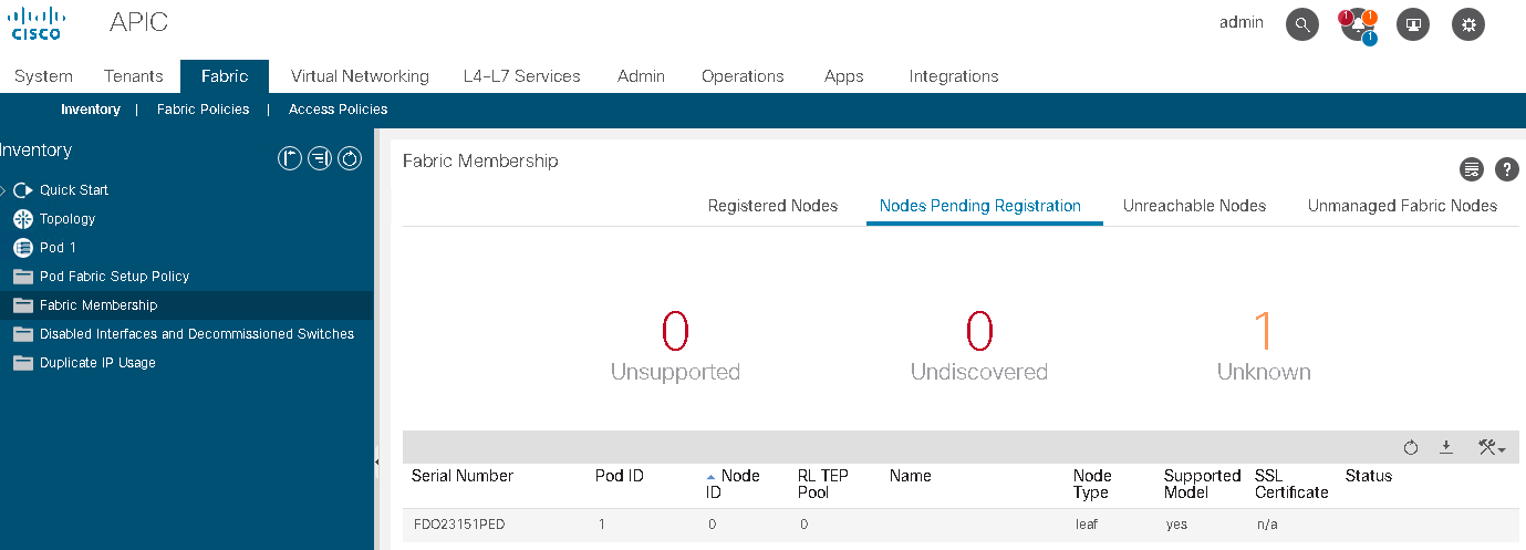
To register the first node, click on the first row, then from the Actions menu (Tool Icon) select Register.
For each node, you need to enter node ID, node name, and pod ID. You should use node ID numbers greater than 101, because Cisco APIC cluster nodes use ID numbers between 1 and 100. Use ID numbers in a continuous range that is different for leaf and spine nodes to make configurations more readable. It is a common practice for leaf switches in Pod 1 to be assigned node IDs 1xx, spine switches in Pod 1 IDs 10xx, leaf switches in Pod 2 IDs 2xx, spine switches in Pod 2 IDs 20xx, etc. You can implement your own scheme to accommodate your own numbering convention or larger fabrics.
After the registration details have been submitted, the entry for this leaf will move from the Nodes Pending Registration tab to the Registered Nodes tab under Fabric Membership. The node takes 3–4 mins to complete the discovery which includes the DHCP and basic policy exchange. During the process, you will notice that a TEP address is assigned. The address is pulled from the available address in your Infra TEP pool.
After the first leaf has been discovered and moved to an active state, it will then discover every spine switch that it is connected to. Because each leaf switch connects to every spine switch, after the first spine completes the discovery process, you should see all the remaining leaf switches that are pending registration. Then go ahead and register all the remaining nodes and wait for all switches to transition to an active state.
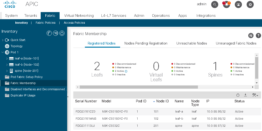
You may use the acidiag fnvread Cisco APIC shell command to verify the state and role of a node. Fabric inventory includes all nodes, interfaces, and fabric member node state information.