CCNP Data Center 300-610 [DCID] Describing High Availability on Layer 2
![300-610 [DCID] Describing High Availability on Layer 2](https://itexamtools.com/wp-content/uploads/2020/08/CCNP_CCIE-300-610-DCID-QA-and-More....-1-1.jpg)
In this Learning session, we’ll be looking at features of Cisco network platforms that provide for high availability, in this case, high availability at layer 2. We’ll begin by looking at the Spanning Tree Protocol introduced in the 1980s by a brilliant woman named Radia Perlman. Spanning Tree Protocol gives us the ability to include resilient links without having the unfortunate behavior of ethernet of sending traffic endlessly in looping paths.
We’ll look at some more recent layer 2 high availability features introduced by Cisco on the Nexus 7000 and 5000 family of platforms, referred to as the virtual port channel. Virtual port channels implement functionality, first added in the IEEE 8023AD– sorry 8021AD and later the 8021AX standard, but modifies it somewhat to allow for this triangle pattern of devices to communicate over this virtual port channel without, once again, having endless looping traffic running through our networks.
Layer 2 packet forwarding or, simply, switching is a critical aspect of the data center network, and high availability should be part of your network design approach. You can use various technologies to reach high availability such as Spanning Tree Protocol (STP), UniDirectional Link Detection (UDLD) protocol, loop guard, root guard, Bridge Protocol Data Unit (BPDU) guard, bridge assurance, and virtual port channel (vPC). STP was implemented to provide a loop-free network at Layer 2. vPC combines the benefits of hardware redundancy with the benefits of port channel loop management, while making it possible to actively use all the available bandwidth.
Now we’re going to look at some of the details of Cisco Layer 2 High-availability Features. We begin with the Spanning Tree Protocol. Cisco implemented, years ago, a Per-VLAN Spanning Tree implementation, meaning that there’s a separate Spanning Tree process running on the switch CPU for each VLAN that we create. We refer to that as the Per-VLAN Spanning Tree.
With the introduction of a variety of Cisco Spanning Tree enhancements to the IEEE Spanning Tree, the standard became Rapid Spanning Tree. Because Cisco still implements Spanning Tree on a per-VLAN basis, we refer now to the Rapid Per-VLAN Spanning Tree Plus. All of that put together is the default Spanning Tree functionality on the Nexus platforms that we’ll be discussing for data center design.
Here, a little illustration of Rapid Spanning Tree. In a topological loop environment, when this switch, for instance, has traffic to send to some device that’s hanging off of that switch, he would send it over the forwarding interface. The forwarding interface is decided based upon a topological discovery involving Layer 2 frames that we refer to as Bridge Protocol Data Units or BPDUs.
Now, when a forwarding interface has a problem, for instance, there’s a fiber break or someone unplugs a connection on an existing switch, the Rapid Spanning Tree recognizes other available paths. Those paths would be referred to as alternate paths through the network. And forwarding will very quickly failover to the alternate paths. All of the MAC address information previously learned on the previous forwarding path is discarded and is relearned over the alternate path.

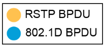
In a Rapid Spanning Tree implementation, we have to take into account the fact that there may be devices that do not implement a Rapid Spanning Tree, a third-party switch or even a host that’s actually running a layer 2 BPDU functionality on it. In that case, Cisco’s Rapid PVST+ has the ability to fall back to the classic IEEE 802.1D Spanning Tree, the original Spanning Tree spec, as introduced by Radia Proman years and years ago. That functionality does not impede the ability to run a Rapid Spanning Tree in the rest of the environment.
There is another IEEE standard Spanning Tree that doesn’t use the Cisco proprietary extensions in the Rapid PVST+. That’s referred to as the Multiple Spanning Tree, the IEEE 802.1W standard. Multiple Spanning Tree, like the Per-VLAN Cisco implementation, allows for greater scalability by including one or more VLANs in the same Spanning Tree process running on a switch CPU. The Multi Spanning Tree is the Spanning Tree of choice when you’re building an environment that has third-party devices that are Rapid Spanning Tree capable.
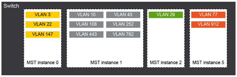
Here’s an example of a Rapid Spanning Tree design in a third-party data center environment where we’re using the Multiple Spanning Tree. In this illustration, we have, for instance, one Multi Spanning Tree instance that has three different VLANs, all following the same Spanning Tree topology. Another Spanning Tree instance with six VLANs, here a single VLAN, and two VLANs. Each of these topologies has its own Spanning Tree process running on switch CPUs.
Because it’s an IEEE standard, both Cisco devices and devices from other manufacturers can participate in this environment. Another advantage of the Multi Spanning Tree is the ability to violate, if it’s necessary, the seven-hop limitation in a Spanning Tree. The way we do that is by having separate Spanning Tree instances and their seven-hop diameters interact at a border between Multi Spanning Tree instances.
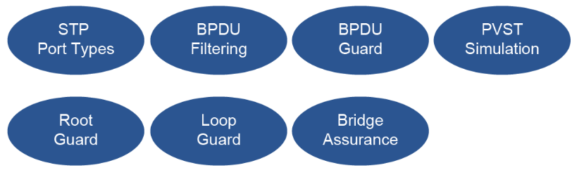
Cisco, over the years, has added a number of additional technologies to the Spanning Tree. Many of these are incorporated in the Rapid Spanning Tree, the IEEE standard, and some of them also in the Multi Spanning Tree IEEE standard. Amongst these introduced benefits, I suppose, are different Spanning Tree port types. The Rapid Spanning Tree depends upon the ability to distinguish between point-to-point network ports, and multi-access ports, and edge ports.
In older Cisco switch products, the Catalyst line, for instance, a feature referred to as PortFast allowed us to recognize an edge port, and on that edge port, immediately move to forwarding state without going through the 15 second of listening state and 15 second of learning state. That’s one of the things that makes Rapid Spanning Tree so rapid. In more modern implementations like the Cisco Nexus product line, we don’t refer to these as PortFast interfaces. We refer to them as edge interfaces. And if we’re going to run multiple VLANs in a trunk on an edge interface, then we refer to that as an edge trunk interface.
BPDU filtering, another Cisco innovation added to the Spanning Tree Protocol, allows me to withhold BPDUs on a particular port and not receive or not recognize any BPDUs coming from that port. It protects my Spanning Tree environment, for instance, from perhaps misconfigured devices that are attached to my Layer 2 network but maybe not under my administrative control. BPDU filtering, in fact, is implemented when we declare an interface to be an edge port. And that protects the device that should be connected to a host from accidentally being connected, say, to another switch and causing a looping of traffic.
On the older PortFast mechanism, we actually were a little more drastic than BPDU filtering. We actually implemented the BPDU Guard. BPDU Guard is more drastic, I say, because when I receive a BPDU on an interface that has BPDU Guard enabled, I will actually error disable that interface so that there’s no possibility of having a topological loop.
The Root Guard functionality prevents a superior BPDU, as it’s called, from causing a topology change and moving the root switch of the Spanning Tree environment from the current device to some downstream device. Again, if I’m connecting switches that I do not have administrative control over to my administrative environment, I would perhaps want to implement the Root Guard and prevent that downstream device maybe from being misconfigured as the root device.
Loop Guard and Bridge Assurance are actually fairly similar protections. They both protect us against the possibility of a uni-directional link, which is not unusual in a fiber environment where one strand of glass, say, the transmitting strand, has a problem. And so my neighboring device cannot receive BPDUs or other traffic, while the receive strand of glass is working just fine.
The device doesn’t know that there is only a one-way connection there. And so looping of traffic can occur. The Loop Guard looks at an interface on the locally configured switch. And when we receive traffic on an interface that is not a root port or a designated port, we will go ahead and refuse to carry that traffic, which, as the name implies, prevents a loop.
Bridge Assurance operates, by default, on the Nexus equipment on all type network interfaces. And it protects us against a uni-directional connection or a software failure on our neighboring device. In the case of Bridge Assurance, if I am not receiving BPDUs on a particular designated or root port, I will put that port into a blocking state so that I don’t retransmit any traffic that’s being inappropriately sent to me.
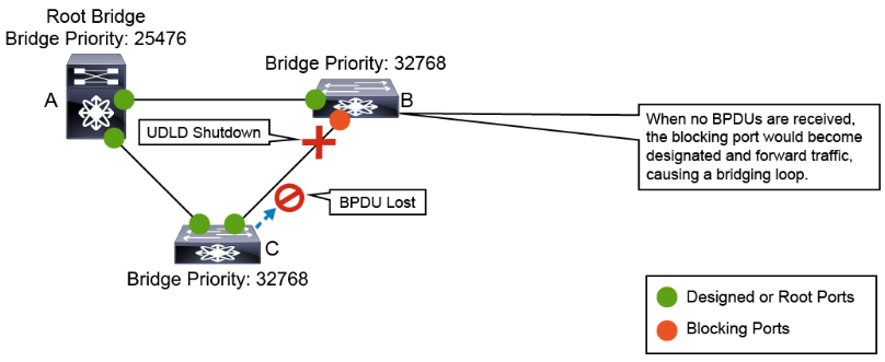
Here’s another layer to high-availability mechanism that’s designed to speed up failure detection in my switched environment. This is referred to as UDLD or UniDirectional Link Detection. Again, the problem in a fiber environment is that one strand of glass may be working just fine, while the other strand is misbehaving. In UDLD, I can recognize those sorts of failures by establishing a protocol exchange mechanism between two devices, in this case, between switch B and switch C.
So I’m going to be sending BPDU frames of traffic from both sides. When one side stops receiving those frames– and we can tune this much faster, by the way, than the two-second interval typical for BPDUs. But when I stop receiving the UDLD keepalives from one direction or another, I can very quickly declare that interface to fail and allow, perhaps, for an alternate path to go into the forwarding state. UDLD, once again, operates at Layer 2. There’s a Layer 3 mechanism that’s very similar, Bidirectional Forwarding Detection.
Cisco Layer 2 high availability is optimized by tools and protocols that provide failovers and fallbacks transparently and quickly. STP provides protection from Layer 2 loops in the networks. Rapid Per VLAN Spanning Tree Plus (Rapid+) is an updated implementation of STP that allows you to create one spanning-tree topology for each VLAN. Rapid+ is the default STP mode on the device. Multiple Spanning Tree (MST), which is the Institute of Electrical and Electronics Engineers (IEEE) 802.1s standard, allows you to assign two or more VLANs to a spanning-tree instance.
The IEEE 802.1D STP standard was designed when recovering within 1 minute after an outage was considered adequate performance. With Layer 3 switching in LAN environments, bridging and switching methods now compete with routed solutions such as Open Shortest Path First (OSPF) and Enhanced Interior Gateway Routing Protocol (EIGRP) to provide alternate paths quicker than was previously possible.
Cisco enhanced the original IEEE 802.1D specification by enabling IEEE 802.1D to operate on a per-VLAN basis, and introduced extensions such as UplinkFast, BackboneFast, and PortFast, and created Per VLAN Spanning Tree (PVST)+. These extensions were designed to accelerate the convergence time of Layer 2 switched networks. The disadvantage of these solutions is that they are proprietary solutions and require additional configuration to tune their performance.
The software can interoperate with legacy IEEE 802.1D systems and the system runs Rapid PVST+ and MST. Rapid PVST+ is the default STP protocol for Cisco Nexus Switches.

Rapid PVST+
The IEEE 802.1w Rapid Spanning Tree Protocol (RSTP) standard is an evolution of the IEEE 802.1D standard. Much of the terminology and parameters remain unchanged in IEEE 802.1w, making it easy for users to configure the optimized protocol. Usually, RSTP performs better than Cisco proprietary extensions without the additional configuration. Rapid PVST+ is the IEEE 802.1w (RSTP) standard that is implemented per VLAN. A single instance of STP runs on each configured VLAN (if you do not manually disable STP). Each Rapid PVST+ instance on a VLAN has a single root switch. You can enable and disable STP on a per-VLAN basis when you are running Rapid PVST+.
When primary link, that was in STP forwarding (FWD) state fails, RTSP failover occurs rapidly. The failover port that was in STP blocking (BLK) state, becomes forwarding port so that the connectivity is fully operational again.

Rapid PVST+ allows the use of the IEEE 802.1w protocol with Cisco PVST+ to provide a much faster convergence per VLAN. With Rapid PVST+, each STP instance uses the IEEE 802.1w algorithm to re-converge the network following link failure. Rapid PVST+ supports one STP instance for each VLAN. Rapid PVST+ uses point-to-point wiring to provide rapid convergence of the spanning tree. The spanning-tree reconfiguration can occur in less than 1 second with Rapid PVST+ (in contrast to 50 seconds with the default settings in the 802.1D STP).
Using Rapid PVST+, STP convergence occurs rapidly. Each designated or root port in the STP sends out a bridge protocol data unit (BPDU) every 2 seconds by default. On a designated or root port in the topology, if hello messages are missed three consecutive times, or if the maximum age expires, the port immediately flushes all protocol information in the table. A port considers connectivity to its direct neighbor root or designated port lost if it misses three BPDUs or if the maximum age expires. This rapid aging of the protocol information allows quick failure detection. The switch automatically checks the port VLAN ID (PVID).
Rapid PVST+ provides for rapid recovery of connectivity following the failure of a network device, a switch port, or a LAN. It provides rapid convergence for edge ports, new root ports, and ports that are connected through point-to-point links as follows:
- Edge ports: When you configure a port as an edge port on an RSTP switch, the edge port immediately transitions to the forwarding state. (This immediate transition was previously a proprietary Cisco feature named PortFast.) You should only configure on ports that connect to a single end station as edge ports. Edge ports do not generate topology changes when the link changes. Enter the
spanning-tree port typeinterface configuration command to configure a port as an STP edge port. - Root ports: If Rapid PVST+ selects a new root port, it blocks the old root port and immediately transitions the new root port to the forwarding state.
- Point-to-point links: If you connect a port to another port through a point-to-point link and the local port becomes a designated port, it negotiates a rapid transition with the other port by using the proposal-agreement handshake to ensure a loop-free topology.
Rapid PVST+ achieves rapid transition to the forwarding state only on edge ports and point-to-point links. Although the link type is configurable, the system automatically derives the link type information from the duplex setting of the port. Full-duplex ports are assumed to be point-to-point ports, while half-duplex ports are assumed to be shared ports.

Edge ports do not generate topology changes, but all other designated and root ports generate a topology change (TC) BPDU when they either fail to receive three consecutive BPDUs from the directly connected neighbor or the maximum age times out. At this point, the designated or root port sends out a BPDU with the TC flag set. The BPDUs continue to set the TC flag as long as the TC While timer runs on that port. The value of the TC While timer is the value set for the hello time plus 1 second. The initial detector of the topology change immediately floods this information throughout the entire topology.
When Rapid PVST+ detects a topology change, the protocol does the following:
- It starts the TC While timer with a value equal to twice the hello time for all the nonedge root and designated ports, if necessary.
- It flushes the MAC addresses that are associated with all these ports.
The topology change notification floods quickly across the entire topology. The system flushes dynamic entries immediately on a per-port basis when it receives a topology change.

Cisco Nexus Series Switches do not support classical IEEE 802.1D spanning tree. The Rapid PVST+ protocol is capable of reverting to traditional IEEE 802.1D behavior for interoperability with traditional bridges on a per-port basis. Reversion to this mode negates the convergence benefits that the enhanced protocol introduced.
Each port maintains a variable that defines the protocol or mode to run on a corresponding segment. A migration delay timer of 3 seconds is also started when the port comes up. When this timer is running, the current mode (STP or RSTP) that is associated with the port is locked. After the migration delay expires, the port adopts the mode of the next BPDU it receives. If the port changes its operating mode as a result of receiving a BPDU, the migration delay restarts to limit the frequency of possible mode changes.
Traditional STP bridges ignore RSTP BPDUs and drop them. The traditional STP bridge assumes that there are no other bridges on the segment and starts sending out inferior IEEE 802.1D-format BPDUs. Upon receiving these traditional BPDUs, RSTP bridges wait twice for the hello time before changing to IEEE 802.1D mode on that port only. As a result, the traditional IEEE 802.1D bridge begins to receive BPDUs that it can understand.
If the traditional STP bridge is removed from the segment, the RSTP bridge continues to run traditional STP on that port. This behavior occurs because the RSTP bridge has no way of knowing that the traditional bridge has been removed from the segment. Manual intervention is required to restore the ability of a port to detect the current protocol.
Rapid PVST+ and IEEE 802.1w use bits 1 to 6 of the flag byte to add the role and state of the port that originates the BPDU, and the proposal and agreement handshake. Bit 0 is reserved for topology change (TC) and bit 7 is reserved for topology change acknowledgment (TCA).
When a port is in traditional IEEE 802.1D mode, it is also able to process topology change notification (TCN) BPDUs and BPDUs with the TC bit or TCA bit set.

Multiple Spanning Tree
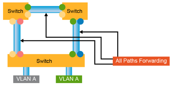
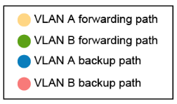
MST maps multiple VLANs into a spanning-tree instance, with each instance having a spanning-tree topology that is independent of other spanning-tree instances. This architecture provides multiple forwarding paths for data traffic, enables load balancing, and reduces the number of STP instances that are required to support many VLANs. MST improves the fault tolerance of the network because a failure in one instance (forwarding path) does not affect other instances (forwarding paths).
MST provides rapid convergence through explicit handshaking because each MST instance uses the IEEE 802.1w standard, which eliminates the 802.1D forwarding delay and quickly transitions root bridge ports and designated ports to the forwarding state.
MST improves spanning-tree operation and maintains backward compatibility with these STP versions:
- Original 802.1D spanning tree
- Rapid PVST+
To allow switches to participate in MST instances, you must consistently configure the switches with the same MST configuration information. A collection of interconnected switches that have the same MST configuration is an MST region. An MST region is a linked group of MST bridges with the same MST configuration.
he MST configuration controls the MST region to which each switch belongs. The configuration includes the name of the region, the revision number, and the MST VLAN-to-instance assignment map.
A region can have one or multiple members with the same MST configuration. Each member must be capable of processing 802.1w BPDUs. There is no limit to the number of MST regions in a network.
Each region can support up to 65 MST instances. Instances can have any identifier number in the range from 1 to 4094. The system reserves Instance 0 for a special instance, which is the Internal Spanning Tree (IST). You can assign a VLAN to only one MST instance at a time.
The MST region appears as a single bridge to adjacent MST regions and to other Rapid PVST+ regions and 802.1D spanning-tree protocols.
The user configures MST, which must be identical on all switches within a single MST region.
You can configure the following three parameters of the MST configuration:
- Name: This 32-character string is null-padded and null-terminated and identifies the MST region.
- Revision number: This unsigned 16-bit number identifies the revision of the current MST configuration. You must set the revision number when required as part of the MST configuration. The revision number is not automatically incremented each time that the MST configuration is committed.
- MST configuration table: This 4096-element table associates each of the potential 4094 VLANs that is supported with a given instance with the first (0) and last element (4095) set to 0. The value of element number X represents the instance to which VLAN X is mapped.
MST BPDUs contain these three configuration parameters. An MST bridge accepts an MST BPDU into its own region only if these three configuration parameters match exactly. If one configuration attribute differs, the MST bridge considers the BPDU to be from another MST region.

STP Extensions
STP extensions are provided to enhance loop prevention and protect against possible user misconfigurations.
The available extensions are spanning-tree edge ports (which supply the functionality that was previously known as PortFast), BPDU filtering, BPDU guard, loop guard, root guard, and bridge assurance. All these extensions can be used with Rapid PVST+ and MST. Many of these features can be applied either globally or on specified interfaces.
Enabling BPDU guard shuts down that interface if a BPDU is received. BPDU guard can be configured at the interface level. In this case, BPDU guard shuts down the port when the port receives a BPDU, regardless of the port type configuration.
BPDU filtering prevents the device from sending or even receiving BPDUs on specified ports. When configured globally, BPDU filtering applies to all operational spanning-tree edge ports. You should connect edge ports only to hosts, which typically drop BPDUs. If an operational spanning-tree edge port receives a BPDU, it immediately returns to a normal spanning-tree port type and moves through the regular transitions. In that case, BPDU filtering is disabled on this port, and spanning tree resumes sending BPDUs on this port. In addition, you can configure BPDU filtering on the individual interface. When you explicitly configure BPDU filtering on a port, that port does not send any BPDUs and drops all BPDUs that it receives. This BPDU filtering command on the interface applies to the entire interface, whether the interface is trunking or not.
When root guard is enabled on a port, it does not allow that port to become a root port. If a received BPDU triggers an STP convergence that makes the designated port become a root port, that port is put into a root-inconsistent (blocked) state. After the port stops sending superior BPDUs, the port is unblocked again. Through STP, the port moves to the forwarding state. Recovery is automatic.
Loop guard helps prevent bridging loops that could occur because of a unidirectional link failure on a point-to-point link. An STP loop occurs when a blocking port in a redundant topology erroneously transitions to the forwarding state. Transitions usually result from a port in a physically redundant topology (not necessarily the blocking port) that stops receiving BPDUs.
You can use bridge assurance to protect against certain problems that can cause bridging loops in the network. Specifically, you use bridge assurance to protect against a unidirectional link failure and a device that continues to forward data traffic when it is no longer running the spanning-tree algorithm.
Bridge assurance is enabled by default and can only be disabled globally. Bridge assurance can be enabled only on spanning-tree network ports that are point-to-point links. Finally, both ends of the link must have bridge assurance enabled.
With bridge assurance enabled, BPDUs are sent out on all operational network ports, including alternate and backup ports, for each hello time period. If the port does not receive a BPDU for a specified period, the port moves into the blocking state and is not used in the root port calculation. Once that port receives a BPDU, it resumes the normal spanning-tree transitions.
A spanning-tree port can be configured as an edge port, a network port, or a normal port. A port can be in only one of these states at a given time. The default spanning-tree port type is normal.
STP edge ports connect only to Layer 2 hosts. The edge port interface immediately transitions to the forwarding state, without moving through the blocking or learning states. (This immediate transition was previously configured as the Cisco proprietary feature PortFast.)
Interfaces that are connected to Layer 2 hosts should not receive STP BPDUs.
MST interoperates with Rapid PVST+ with no need for user configuration. The PVST simulation feature enables this interoperability. PVST simulation is enabled by default when you enable MST. By default, all interfaces on the device interoperate between MST and Rapid PVST+.

However, you may want to control the connection between MST and Rapid PVST+ to protect against accidentally connecting an MST-enabled port to a port that is enabled to run Rapid PVST+. Because Rapid PVST+ is the default STP mode, you may encounter many Rapid PVST+ connections.
Disabling Rapid PVST+ simulation, which can be done per port or globally for the entire device, moves the MST-enabled port to the blocking state once it detects that it is connected to a Rapid PVST+-enabled port. This port remains in the inconsistent state until the port stops receiving Rapid PVST+ and STP BPDUs, and then the port resumes the normal STP transition process.
The root bridges for all STP instances must all be in either the MST region or the Rapid PVST+ side. If the root bridges for all STP instances are not on one side or the other, the software moves the port into a PVST simulation-inconsistent state.
UniDirectional Link Detection
You can use UDLD to ensure a physical connection of the cables. If you connect two devices (A and B in the figure) with a pair of optical fibers, one is used for sending from A to B, while the other from B to A, making this link bidirectional. If one of these fibers breaks down, the link becomes unidirectional. UDLD detects such line breaks and shuts down the port. It can also generate syslog entries.
UDLD works with Layer 1 protocols to determine the physical status of a link. At Layer 1, autonegotiation manages physical signaling and fault detection. At Layer 2, UDLD performs tasks that autonegotiation cannot perform. These tasks include detecting the identities of neighbors and shutting down misconnected LAN ports. When you enable autonegotiation and UDLD, Layer 1 and Layer 2 detection functions work together to prevent physical and logical unidirectional connections and the malfunctioning of other protocols.
Devices periodically transmit UDLD packets to their neighbor devices on LAN ports with UDLD enabled. If the packets are echoed back without a specific acknowledgment (echo), the link is then marked as unidirectional and the port is shut down. Devices on both ends of the link must support UDLD for the protocol to successfully identify and disable unidirectional links.
A good practice is to use UDLD in data centers. To do so on Cisco Nexus switches, you need to enable UDLD with the command. With this action, all 10-Gb interfaces use UDLD automatically. However, for 1 Gb interfaces, you must enable UDLD manually per-interface because it is disabled by default. You might also want to go from the default normal mode to the aggressive mode, which actively tries to re-establish the connection with the affected neighbor, should the connection break down. After eight unsuccessful retries, UDLD disables the port. You can use the aggressive mode on point-to-point links between network devices that support it.
Content Review Question
Which three configuration attributes in MSTP must match between two switches to become members of the same region? (Choose three.)
- common spanning-tree instance
- region-name
- master name
- revision number
- MSTP domain
- root path cost
- STP instance mappings for each VLAN
- VLAN mappings to STP instance numbers
Answer
The correct answers are: “region name,” “revision number,” and “VLAN mappings to STP instance numbers.” An MST region is a linked group of MST bridges with the same MST configuration. You can configure the following three parameters of the MST configuration: Name: This 32-character string is null-padded and null-terminated and identifies the MST region; Revision Number: This unsigned 16-bit number identifies the revision of the current MST configuration. You must set the revision number when required as part of the MST configuration. The revision number is not incremented automatically each time that the MST configuration is committed; MST configuration table: This 4096-element table associate each of the potential 4094 VLANs that is supported with a given instance with the first (0) and last element (4095) set to 0. The value of element number X represents the instance to which VLAN X is mapped.