VCAP5-DCA configure using vSphere
This chapter provides the knowledge and skills needed to VCAP5-DCA configure using vSphere, successfully configure and administer an enterprise network that includes virtual networks built using vSphere.
This class covers the following subjects:
- Implement and Manage Complex Virtual Networks—This section identifies common virtual switch settings and provides steps for configuring and managing standard and distributed virtual switches (vSwitches).
- Configure and Maintain VLANs, PVLANs, and VLAN Settings—This section provides steps for configuring VLANs and PVLANs and explains how to recognize potential use cases.
- Deploy and Maintain Scalable Networking—This section provides steps for configuring NIC Teaming policies and explains the corresponding physical switch settings.
- Administrator vSphere Distributed Switches—This section identifies settings and features that are specific to distributed vSwitches (vDS) and provides steps for implementing each feature.
This chapter covers a portion of the VCAP-DCA Exam objectives 2.1, 2.2, 2.3, and 2.4.
so, this chapter is intended to provide you with the knowledge and skills to successfully perform the administration of an enterprise network that includes virtual networks built using vSphere.
It is also intended to ensure that you have the skills to successfully complete network configuration, troubleshooting, and management tasks that might be part of the VCAP5-DCA exam.
As you read this chapter, take time to practice the steps provided until you are confident that you can perform such tasks rather quickly without any assistance.
Some steps involve using the vSphere Client; others involve using the vCLI and PowerCLI.
[ufwp id=”1316004″]
“Do I Know This Already?” Quiz
The “Do I Know This Already?” quiz allows you to assess how well you already know the material in this chapter.
Table 2-1 outlines the major headings in this chapter and the corresponding “Do I Know This Already?” quiz questions.
You can find the answers in Appendix A, “Answers to the ‘Do I Know This Already?’ Quizzes.”
Because of the advanced and hands-on nature of this particular exam, you should read the entire chapter and practice performing all the described tasks at least once.
so, regardless of how well you do on this quiz.
This quiz can be helpful to determine which topics will require the most effort during your preparation.
Table 2-1 “Do I Know This Already?” Foundation Topics Section-to-Question Mapping
| Foundations Topics Section | Questions Covered in This Section |
| Implement and Manage Complex Virtual Networks | 1,2 |
| Configure and Maintain VLANs, PVLANs, and VLAN Settings | 3,4 |
| Deploy and Maintain Scalable Networking | 5,6 |
| Administer vSphere Distributed Switch Settings | 7,8 |
- Which method can be used to successfully enable SNMP Traps?
- Select Administration > vCenter Server Settings, and then check the Enable SNMP Traps check box.
- Use the vSphere Client to log on directly to an ESXi host, and then
- check the Enable SNMP Traps check box on the Configuration tab.
- Use the Set_AdvancedSetting PowerCLI cmdlet.
- Use the esxcli system snmp set command.
- Which method can be used to successfully enable Direct Path I/O?
- From an ESXi host’s Configuration tab, check the Enable Direct Path I/O box.
- From an ESXi host’s Configuration tab, click Hardware > Advanced Settings.
- From vCenter Server, enable and configure Network I/O control.
- From vCenter Server, enable Direct Path I/O from Administration > Advanced Settings.
- Which method can be used to assign VLAN tagging on a standard vSwitch (vSS) port group?
- Use the Set-Vlan cmdlet on an object variable that represents a vSS port group.
- Select a vSS, choose Edit, and enter a VLAN number to assign to the vSwitch.
- Use the esxcli network vswitch standard portgroup set command.
- Select a vSS port group, select Edit, and select a VLAN tagging method.
- Which method can be used to configure the VLAN settings of a vDS port group where a Wireshark VM will be used to inspect network packets to and from all other VMs connected to all other port groups and VLANs on the same vDS?
- Set the VLAN on the port group to 4096.
- Set the VLAN Type to VLAN Trunking.
- Set the VLAN Type to Promiscuous.
- Set the VLAN Type to PVLAN.
- Which method can be used to connect a vSS port group to two uplink ports that are configured with EtherChannel?
- Change the Load Balancing Policy to Route based on the originating port ID on the vSS.
- Change the Load Balancing Policy to Route based on the originating virtual switch port ID on the vSS port group.
- Change the Load Balancing Policy to Route based on Physical NIC Load on the vSS port group.
- Change the Load Balancing Policy to Route based on IP Hash on the vSS.
- Which method can be used to configure a port group to support Microsoft Load Balancing unicast mode?
- Set Notify Switches to No.
- Set Load Balancing Policy to Route based on IP Hash.
- Set VLAN to 4095.
- Set Beacon Probing to Link Status Only.
- Which method can be used to create user-defined custom network resource pools?
- On the properties page of a distributed switch, check the Enable Network Resource Pools box. Then use the Create Network Resource Pool link.
- Use the New-ResourcePool cmdlet to create the pool, and use the Set-ResourcePool cmdlet to set the pool type to Network.
- On the Resource Allocation tab, check the Enable Network IO Control box. Select the New Network Resource pool link.
- On the Resource Pools tab, click the Create Network Resource Pool link.
- Which of the following summarizes the steps that should be followed to allow a Wireshark VM connected to a vDS to inspect packets to and from just one other specific VM on the same vDS?
- Set VLAN Type to Trunking, and then enable Promiscuous Mode.
- Configure Port Mirroring.
- Edit the settings of the monitored VM and configure port replication.
- Configure NetFlow.
[ufwp id=”3703756″]
Foundation Topics- VCAP5-DCA configure using vSphere
Implement and Manage Complex Networks
This section is intended to provide you with the knowledge and skills to successfully configure and manage virtual switches that are implemented in a complex network.
Details on concepts and implementation are provided, along with the steps necessary to perform key configuration and administration tasks.
The examples and scenarios in this chapter utilize the vSphere Client, the vCLI, and PowerCLI.
Overview
You should already be familiar with basic vSphere network virtualization concepts and administrative tasks.
If any of the following details in this overview are new to you, be sure to research the appropriate information before continuing on to the remainder of this chapter.
vSphere Standard Switches (vSSes) are implemented on each ESXi host in a vSphere implementation.
These Layer-2, software-based switches provide the following features: VLAN Tagging, Security, NIC Teaming, Failover, and Traffic Shaping.
All these features have settings that can be configured using the vSphere Client. On each vSS, one or more port groups can be configured.
These port groups can support virtual machines and manage traffic and services like vMotion, IP storage, and FT logging.
The default settings for the Security, Teaming, and Shaping policies can be modified per VSS and can be overridden per port group.
VLAN settings can be configured on each port group. Some settings, such as Maximum Transmission Unit (MTU) and Cisco Discovery Protocol (CDP), can be configured only at the VSS level.
Prior to attaching virtual machines to a network, a VM port group must be created on a vSS.
The port group is then configured with the VLAN, Traffic Shaping, Security, and physical NIC Teaming settings.
Finally, the vmnic on the virtual machine is connected to the appropriate port group.
Management traffic and all other network services, including vMotion, IP-based storage, VMware HA heartbeats, and VMware Fault Tolerance logging, require a vmkernel port.
When a vmkernel port is created on a vSS, a port group is first created; then a vmkernel virtual adapter is created and placed in the port group.
When using the vSphere Client, the port group creation for vmkernel ports is transparent.
When using the vCLI, the port group must first be created.
vSphere Distributed Virtual Switches (vDSes) are implemented at the datacenter level, where vCenter Server controls the configuration and management of the vDS.
ESXi hosts are then attached to these vDSes.
When a host is connected to a vDS, vCenter Server creates a data plane at the ESXi host level by creating one or more hidden vSwitches.
The settings and statistics of the hidden vSwitch(es) are automatically synchronized with those on the vDS.
The data plane and packet movement are controlled by the hidden vSwitch(es) at the ESXi host level,
which ensures that any disruption of the connection between the ESXi host and vCenter Server does not affect the network connectivity of the VMs.
The control plane is handled by the vCenter Server. So, any loss of connectivity between the ESXi host and vCenter Server will affect the ability to make modifications to the vDS.
As mentioned earlier, all ports on a vSS or vDS are created from a port group.
Although it can appear that a vmkernel port created using the vSphere Client is created without a port group, it is actually created as part of the operation.
This port group is used only for the vmkernel port. Policies can be configured for the vmkernel, but they are actually configured on the port group—not the vmkernel virtual adapter.
This bit of detail might be new to you concerning vSSes, but it should seem familiar to those who configure vDSes.
because, in the vSphere Client, port groups must first be configured on a vDS prior to attaching vmkernel virtual adapters.
vSSes can be managed by selecting the appropriate ESXi host and using the Configuration Tab > Networking option, as shown in Figure 2-1.
)
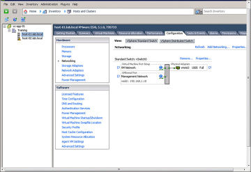
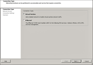
The Add Networking link can be used to launch a wizard to create a new vSS.
The first page of the wizard is the Connection Type page, as shown in Figure 2-2.
)
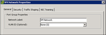
The properties of a vSS can be overridden per port group.
The General tab can used to set the Network Label and VLAN ID of the port group, as shown in Figure 2-3.
)
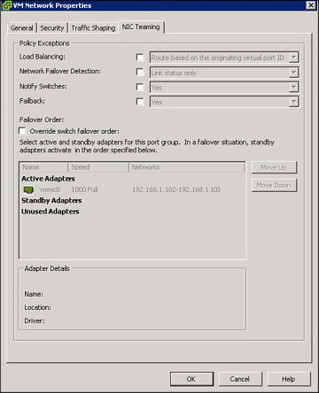
The Load Balancing, Failover Detection, Notify Switches, Failback, and Failover Order settings can be configured on the NIC Teaming properties tab of a port group or the vSS, as shown in Figure 2-4.
)
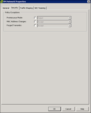
Security policy settings, such as Promiscuous Mode, can be set on the Security properties page of a port group or the vSS, as shown in Figure 2-5.
)
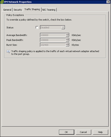
Traffic Shaping policy settings, such as Average Bandwidth and Peak Bandwidth, can be set on the Traffic Shaping properties page of a port group or the vSS, as shown in Figure 2-6.
)
vDSes can be managed using the vSphere Client by connecting to a vCenter Server and navigating to the Inventory > Networking section.
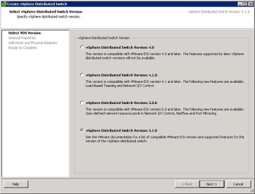
You can right-click a datacenter object and select New vSphere Distributed Switch to launch the Create vSphere Distributed Switch wizard, as shown in Figure 2-7.
)
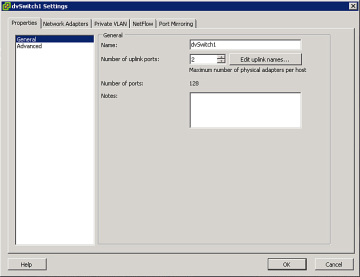
To configure a vDS, right-click the vDS and select Edit Settings.
General settings, such as the Name and number of uplink ports, can be set on the General properties page of the vDS, as shown in Figure 2-8.
)
Policy inheritance on a vDS differs significantly from vSphere Standard Switches.
Most policies that affect a vDS port group cannot be set at the vDS level.
and Instead, properties can either be set at the individual port group level or be managed at the vDS level using the Manage Port Groups menu shown in Figure 2-9.
)
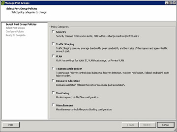
All the policies that can be configured on a vDS port group are shown.
Selecting any Policy Category (or categories) and clicking Next allows the related policy settings to be applied to one or more vDS port groups.
An example of this is shown in Figure 2-10.
)
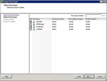
To configure the selected policies, select the vDS port groups to configure and then click Next. The Configure Policies screen is displayed, as shown in Figure 2-11.
)
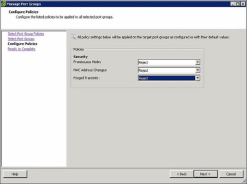
The vDS Configure Policies page allows you to adjust the settings for all the policies you selected and will apply those changes to the port groups you have chosen.
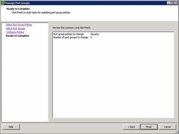
The final screen summarizes the changes that will be applied, as shown in Figure 2-12.
)
Of course, individual vDS port groups can be configured.
To do so, right-click the vDS port group and select Edit Settings.
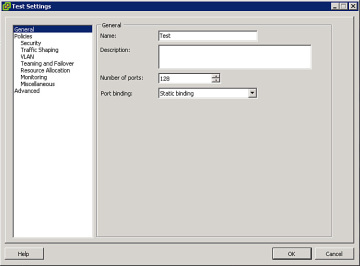
The General properties page of the vDA port group is shown and can be used to set the Name, Number of Ports, and Port Binding option, as shown in Figure 2-13.
)
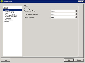
Security policy settings, such as Promiscuous Mode, can be set on the Security properties page of the vDS port group shown in Figure 2-14.
)
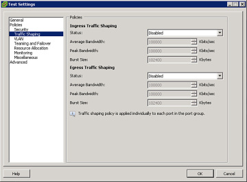
Traffic Shaping policy settings, such as Average Bandwidth and Peak Bandwidth on ingress and egress traffic, can be set on the Traffic Shaping properties page of a distributed port group, as shown in Figure 2-15.
)
The same process can be used to adjust the VLAN, Teaming and Failover, Resource Allocation, Monitoring, and other settings.
After creating and configuring a vDS, ESXi hosts are added.
Adding the host creates the data plane and applies the settings from the vDS to the host.
To connect an ESXi host, right-click the vDSS and select Add Host, which launches the Add Host to vSphere Distributed Switch wizard shown in Figure 2-16.
)
Select the hosts to be added and choose the vmnics that the vDS will utilize.
The remainder of this chapter focuses on specific, advanced administration tasks, including commands that are called out on various VCAP5-DCA Exam Blueprint objectives.
These tasks include configuring SNMP using commands and migrating objects from vSSes to vDSes.
Configure SNMP [ VCAP5-DCA configure using vSphere]
Typically, administrators are required to automatically retrieve status information from vSphere and to feed this data to monitoring and management systems.
This can be accomplished using SNMP.
A vCenter Server can be configured to send SNMP traps to management systems that use SNMP receivers.
A maximum of four SNMP receivers can be configured per vCenter Server. The required privilege is Global.Settings.
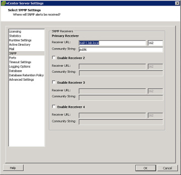
The procedure for configuring SNMP receivers on a vCenter Server using the vSphere Client is as follows:

- Step 1. Select Administration > vCenter Server Settings.
- Step 2. Select SNMP.
- Step 3. In the Receiver URL fields, enter the hostname or IP address of the SNMP receiver.
- Step 4. In the adjacent field, enter the port number used by the receiver, which must be between 1 and 65535.
- Step 5. In the Community field, enter the community identifier.
- Step 6. Click OK.
This is shown in Figure 2-17.
)
The Get-AdvancedSettings and Set-AdvancedSettings PowerCLI cmdlets can be used to query and configure SNMP on a vCenter Server.
The value for the Entity parameter should be set to the name of the vCenter Server.
and the value for the Name parameter should match the name of an SNMP receiver.
Scenario—Use PowerCLI to Configure SNMP on vCenter
Examine the current SNMP advanced settings on the vCenter Server named vc-app-01.
Set the first SNMP receiver to 192.168.1.10, the community to public, and Enabled to true.
The following commands can be used to accomplish this task:
- Get-AdvancedSetting –Entity vc-app-01 –Name snmp.*
- Get-AdvancedSetting –Entity vc-app-01 –Name
- snmp.receiver.1.community | Set-AdvancedSetting –Value public
- Get-AdvancedSetting –Entity vc-app-01 –Name snmp.receiver.1.name | Set-AdvancedSetting –Value 192.168.1.10
- Get-AdvancedSetting –Entity vc-app-01 –Name snmp.receiver.1.enabled | Set-AdvancedSetting –Value $true
SNMP can also be configured on each ESXi host.
ESXi 5.1 supports SNMP v1, v2, and v3.
The procedure for configuring SNMP v1 on an ESXi host involves configuring the community string, identifying one or more target receivers, enabling SNMP, and testing SNMP using esxcli system SNMP.
For example, the following set of commands can be used to enable, configure, and test SNMP on an ESXi host, where the community is set to public and the target is set to esx-01.lab.local on port 161.
[ufwp id=”3111152″]
- esxcli system snmp set –communities public
- esxcli system snmp set –targets esx-01.lab.local@161/public
- esxcli system snmp set –enable true
- esxcli system snmp test
VMware Direct Path I/O
The main use case for implementing VMware Direct Path I/O for a NIC is to support extremely heavy network activity.
within a VM, when other methods, such as placing the VM on a vSwitch by itself with dedicated NICs, are insufficient.
Direct Path I/O, which is often referred to as passthrough, allows the VM to have direct access to the NIC.
which in turn allows the VM rather than the vmkernel to own and drive the NIC.
Direct Path I/O can also be used for other types of adapters, such as graphic cards.
VMware Direct Path I/O links a virtual machine directly to hardware in a specific ESXi host.
This typically introduces limitations for the affected VM, including the inability to utilize common features on the VM, such as vMotion, suspend, and snapshots.
These limitations can be mitigated if the virtualization platform is a Cisco Unified Computing System (UCS) using Cisco Virtual Machine Fabric Extender (VM-FEX) distributed switches.
The prerequisites for Direct Path I/O are as follows:
- Enable Intel Directed I/O (VT-d) or AMD I/O Virtualization Technology (IOMMU) in the BIOS
- Ensure the VM is utilizing virtual hardware version 7 or higher
The procedure to configure VMware Direct Path I/O involves configuring the PCI device as a pass-through device and assigning it to a specific VM.
The steps to configure these settings using the vSphere Client are shown here:
- Step 1. Select the ESXi host.
- Step 2. Select Configuration tab > Hardware > Advanced Settings.
- Step 3. Select the Pass-through page.
- Step 4. Click Edit.
- Step 5. Select the appropriate PCI device.
- Step 6. Click OK.
- Step 7. Right-click the VM, and then select Edit Settings.
- Step 8. Click the Hardware tab.
- Step 9. Click Add.
- Step 10. Choose the PCI device.
- Step 11. Click Next.
Migrate from Standard to Distributed Virtual Switches – VCAP5-DCA configure using vSphere
VCAP5-DCA configure using vSphere
Migrating a virtual network implementation that is based solely on vSSes to one that includes one or more vDSes is typically not very challenging, but it does require some care.
More than one method exists to make such a migration.
One option is to build a new vDS and then migrate all appropriate items from an existing VSS to the new vDS utilizing a single wizard, available when attaching the ESXi host to the vDS.
The first task when using this method is to the build at least one new vDS. The steps to do this using the vSphere Client are as follows:
- Step 1. Select Home > Network Inventory view.
- Step 2. Right-click the appropriate datacenter where the vDS should be created.
- Step 3. Select New Distributed Virtual Switch.
- Step 4. In the wizard, enter a name for the vDS (such as dvSwitch0) and enter the maximum number of uplinks allowed per ESXi host (such as 2).
- Step 5. Do not attach any hosts or physical adapters at this time.
- Step 6. Accept any defaults related to distributed port groups (this will create a default port group named dvPortGroup that can be renamed and reconfigured later).
- Step 7. Click OK.
Next, attach the ESXi host and migrate all items, including VMs, NICs, and vmkernel ports, from the vSS to the vDS.
This approach works nicely for vSSes configured with IP Hash-based NIC Teaming and Etherchannel. Follow these steps:
- Step 1. In the Inventory pane, click the vDS.
- Step 2. Select the Configuration tab.
- Step 3. Visually examine the diagram to determine whether any port groups exist on the vDS.
- Step 4. Decide which port groups should be configured on the vDS and the specific settings for each port group policy, including VLAN, Security, NIC Teaming, and Traffic shaping policies.
- These ports will act as the destination port groups during the migration.
- Step 5. Modify any existing port groups to match the planned settings for that port group.
- Create all other port groups as planned.
- To create a new port group, right-click the vDS and select New Distributed Port Group.
- Provide a port group name and appropriate settings when prompted by the wizard.
- Step 6. In the Inventory pane, right-click the vDS and select Add Host, which launches the Add Host to vSphere Distributed Switch Wizard.
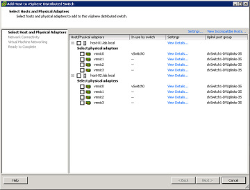
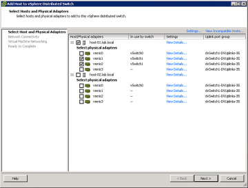
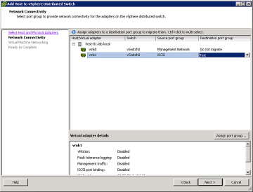
- Step 7. When prompted by the wizard, select the ESXi host and select all the physical adapters that are currently attached to the vSS that is being replaced, as shown in Figure 2-18. Click Next.
)
Step 8. In the next page of the wizard, choose any vmkernel ports (such as VMotion or Management virtual adapters) that you want to migrate from the vSS, as shown in Figure 2-19. In the Destination Port Group column, select the distributed port group where you want to move the vmkernel port.
)
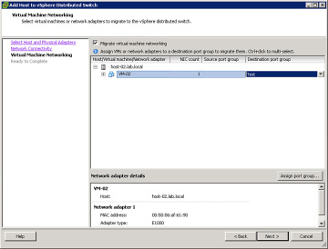
Step 9. In the next page of the wizard, check the box labeled Migrate Virtual Machine Networking. In the Destination Port Group column, select the target distributed port group for each VM, as shown in Figure 2-20.
)
- Step 10. Click Finish. All the selected VMs, vmkernel ports, and NICs should migrate safely to the new vDS with little or no disruption in network connectivity per VM.
Other options to migrate from vSS to vDS exist.
For example, the previous procedure could be modified such that only one NIC (instead of all NICs) from the current vSS is selected in the wizard.
By using this method and ensuring that all VMs and vmkernel virtual adapters have migrated successfully to the vDS prior to migrating the remaining NICs, network connectivity is maintained.
Even during the midst of the migration, where some VMs are still connected to the original vSS and some to the new vDS.
the VMs on either switch is still connected to the network.
Do not use this approach if IP Hash-based NIC Teaming and Etherchannel (IEE802.3ad) are currently in use.
For another example, instead of migrating VMs when attaching the ESXi host, the VMs could be migrated after attaching the host.
This could be accomplished using the Migrate Virtual Machine Networking wizard.
It could also be accomplished by editing each specific VM’s virtual NICs.
Some additional details to consider are:
- When replacing a vSS with a vDS, ensure that you configure the ports on the appropriate vDS port group to match the settings on the original vSS port group.
- These configurations should take into consideration security, traffic shaping, NIC teaming, MTU, and VLAN configurations.
- If spare physical adapters exist, consider connecting those to the new vDS and initially migrating just the VMs and vmkernel ports.
[ufwp id=”3111152″]
Configure Virtual Switches Using CLI Commands VCAP5-DCA configure using vSphere
vSSes can be completely created, configured, and managed from the command line.
So, The main command namespace is esxcli network standard.
Because vDSes are created on a vCenter Server, they cannot be modified using the ESXi shell or the vCLI.
However, the ESXi Shell and the vCLI can be used to identify and modify how an ESXi host connects to a vDS.
The specific namespaces for vSSes and vDSes are respectively:
- esxcli network vswitch standard
- esxcli network vswitch dvs vmware
The esxcli namespace for vSSes provides commands to allow an administrator to examine and configure all settings of a vSS and its port groups.
The volume of commands and options is far too great to provide details and examples for each command, but here is an example of using a set of commands to accomplish a specific task.
Scenario—Create and Configure a Standard Virtual Switch
Create a new vSS named vSwitch1 having 256 ports with support for jumbo frames (MTU=9000). Attach vmnic1 and vmnic2 as uplinks.
Create a port group named Test. Set its VLAN property to 101, and set its NIC Teaming to iphash.
Enable traffic shaping with average and peak bandwidth set to 100 Mbps. Before beginning, ensure that no vSS named vSwitch1 already exists.
This scenario can be accomplished by using these commands:
- esxcli network vswitch standard list
- esxcli network vswitch standard add -P 128 -v vSwitch1
- esxcli network vswitch standard uplink add –u vmnic1 -v vSwitch1
- esxcli network vswitch standard uplink add –u vmnic2 -v vSwitch1
- esxcli network vswitch standard set –m 9000 –v vSwitch1
- esxcli network vswitch standard portgroup add -p Test -v vSwitch1
- esxcli network vswitch standard portgroup set -p Test -v 101
- esxcli network vswitch standard portgroup policy failover set -p Test -l iphash
- esxcli network vswitch standard port group policy shaping set -p Test -e true -k 100000 –b 100000 –t 100000***
When setting traffic shaping from the ESXi Shell, you must set avg (-b), burst (-t), and peak (-k)
The command to identify all VMware vDSes accessed by an ESXi host is esxcli network vswitch dvs vmware list.
Analyze Virtual Switches Using ESXCLI VCAP5-DCA configure using vSphere
VCAP5-DCA configure using vSphere
Commands can also be used to analyze details of existing vSSes and vDSes. For example, to list all vSSes and vDSes, use these commands:
- esxcli network vswitch standard list
- esxcli network vswitch dvs vmware list
To closely examine properties on a specific vSS, the –v argument can be used to identify the vSS.
For example, if iSCSI performance is poor and you suspect that jumbo frames is not properly configured, you might want to examine the MTU settings on a vSS.
For another example, if a VM fails to connect to a vSS, you might need to determine whether all the ports are already used by comparing Used Ports to Configured Ports.
In these and similar cases, you can examine the properties of a vSS named vSwitch1 using this command:
- esxcli network vswitch standard list –v vSwitch1.
Configure NetFlow
NetFlow is an industry standard for collecting and analyzing network data.
It is a collection of related network packets traveling in sequence in the same direction, sharing specific characteristics, including source IP address, target IP address, source port, target port, and type of service.
Ethernet switches that support the NetFlow protocol can be configured to identify net flows and send data about the net flow to net flow receivers.
NetFlow analyzers can be used to analyze the collected data and produce reports.
Some examples of NetFlow analysis products are Solarwinds NetFlow Traffic Analyzer and OptiView NetFlow Tracker.
vSSes cannot be configured for NetFlow collection, but vDSes can.
The steps to configure a vDS for NetFlow collection using the vSphere Client are as follows:
- Step 1. Drill to Inventory > Networking.
- Step 2. Right-click the vDS, and select Edit Settings.
- Step 3. Select the NetFlow tab.
- Step 4. Define the IP and port ID for the NetFlow Collector.
- Step 5. Define the IP for the vSphere Distributed Switch.
- Step 6. Configure any advanced settings as needed (sampling rate, process internal flows only, and so on).
- Step 7. Click OK to save.
- Step 8. Then right-click and select Edit Settings on the dvPort Group on which you want to enable NetFlow.
- Step 9. Click Monitoring.
- Step 10. Use the drop-down menu to give NetFlow a status of Enabled on this port group.
- Step 11. Click OK.
Discovery Protocols
Cisco Discovery Protocol (CDP) can be configured on both vSSes and vDSes.
Link Layer Discovery Protocol (LLDP) can also be configured on vDSSes, but not vSSes.
CDP is a protocol used on Cisco switches to discover identity and configuration information about the switches to which they are attached and broadcast its own information to those switches.
CDP can be used by vSwitches to discover and broadcast information in much the same way.
In addition, in a vSphere implementation, CDP can be used to allow attached Cisco switches to discover information about vSwitches and ESXi hosts.
Similarly, LLDP—a vendor-neutral implementation of CDP—can be used to discover and broadcast the same information on switches that support LLDP rather than CDP.
The main use case for utilizing LLDP is when a network contains non-Cisco switches, but this use case does require vDSes.
The following steps can be used to configure LLDP on a vDS:
- Step 1. Select Inventory > Networking.
- Step 2. Right-click the vDS, and select Edit Settings.
- Step 3. In the Properties tab, select Advanced.
- Step 4. In the Status drop-down menu, select Enabled.
- Step 5. In the Type drop-down menu, select Link Layer Discovery Protocol.
- Step 6. In the Operation drop-down menu, select Listen, Advertise, or Both.
The following command enables CDP and sets it to both on a vSS named vSwitch1:
- esxcli network vswitch standard set –c both –v <vSwitch. Name>
[ufwp id=”3111152″]
Configure and Maintain VLANs and PVLANs
This section is intended to provide you with the knowledge and skills needed to successfully configure Virtual Local Area Networks (VLANs) and private VLANs (PVLANs) in a vSphere network implementation.
Types of VLANs and PVLANs [VCAP5-DCA configure using vSphere]
VLANs are virtual networks that are defined within a LAN. VLANs are often called logical networks and are defined by software within the Ethernet switches.
They provide multiple broadcast domains within a LAN without requiring physical separation.
vSSes and vDSes support VLANs, VLAN tagging, and VLAN trunking as identified by IEEE-802.1q. Each VLAN is assigned an ID number between 1 and 4094.
The VLAN is then typically assigned to a specific IP range.
Switches can be configured to allow and control routing between VLANs as desired.
Various methods can be used to connect VMs and vmkernel ports to specific VLANs.
The most common method is to configure the physical network port for VLAN trunking and then to assign a desired VLAN number(s) to each virtual port group (or vmkernel port).
The VLANs should first be configured on the physical switch if they do not already exist.
This method of VLAN tagging is also known as Virtual Switch Tagging (VST). vSphere supports two other VLAN tagging methods, External Switch Tagging (EST) and Virtual Guest Tagging (VGT).
To configure EST, configure the physical Ethernet switch to assign the VLAN numbers.
No configuration is performed on the vSS or vDS, and packets are not tagged until they reach the physical switch infrastructure.
All virtual machines on all port groups using the vmnic that connects to the physical switch port will reside in that VLAN.
VGT is enabled by configuring the VLAN within the guest OS rather than on the virtual port group.
Packets are tagged before they leave the guest OS.
VMware recommends network segregation between different types of traffic, such as management, vMotion, and VMs.
This can be achieved by using separate VLANs for each network type.
For example, a management VLAN can be created on physical switches and configured accordingly on vSwitches.
You can configure VLANs on port groups on vSSes using the vSphere Client by following these steps:
- Step 1. In the Host and Clusters Inventory, select an ESXi server.
- Step 2. Select Configuration > Networking.
- Step 3. Click the Properties link for the desired vSS.
- Step 4. Select the appropriate port group, and click Edit.
- Step 5. In the General Properties page, enter the appropriate VLAN number.
- Step 6. Click OK.
VLANs can be configured with the esxcli network vswitch standard portgroup command. For example, to assign VLAN 101 to a port group named Test, the command is
- esxcli network vswitch standard portgroup set -p Test -v 101
VCAP5-DCA configure using vSphere
Determine Use Cases for VLAN Trunking VCAP5-DCA configure using vSphere
vSSes permit only one VLAN trunk option on a port group, which is to trunk all VLANs 1 to 4094.
To configure a standard port group to trunk all VLANs, set the VLAN ID to 4095, which is a special VLAN number designed for this purpose.
For example, to connect a VM-based network sniffer (such as Wireshark) to a standard port group.
and configure it to inspect network packets for multiple port groups that are assigned to various VLANs, set the sniffer port group VLAN to 4095.
NOTE
Also set the Security setting of the sniffer port group to allow Promiscuous Mode.
This is necessary to allow the Wireshark VM to inspect packets that are not destined for the sniffer VM.
VST (assigning VLAN numbers to virtual port groups) requires VLAN trunking on the physical switch ports.
The trunk should include all VLANs that will be assigned to the virtual port groups that share the same physical uplinks.
For example, consider this scenario.
Scenario—VLAN Trunking on a Standard Virtual Switch
- The management network is VLAN 101.
- The production network is VLAN 201.
- Both the management vmkernel ports and the production VM port group are configured on the same vSS and share the same NIC team.
In this scenario, the physical switch ports must be configured to trunk VLANs 101 and 201.
The Management Network vmkernel port must be set for VLAN 101.
The production VM port group must be set for VLAN 201.
VLAN trunking is permitted on vDSes, where it is more configurable than VLAN trunking on vSSes.
On vDSes, the VLAN type can be set to VLAN Trunking and the trunk can be set to a combination of specific VLAN values and VLAN ranges.
For example, if the Wireshark VM is needed to inspect packets on VLAN 101 and 201, but not on any other VLAN, then it can be attached to a distributed port group that is trunked for just VLANs 101 and 201.
[ufwp id=”2052309″]
Determine Use Cases for PVLAN Trunking
A PVLAN is typically described as a VLAN within a VLAN. PVLANs are typically referenced using both the primary and secondary VLAN IDs.
For example, within primary VLAN 10, you could create secondary PVLANs 1 through 4094 and identify these PVLANs as 10-1 to 10-4094.
Private VLANs allow secondary VLANs within a primary VLAN that share the same IP subnet.
PVLANs can be configured as Community, Isolated, or Promiscuous.
Objects in the same community PVLAN can communicate with other devices in the same community and in the promiscuous VLAN,
but they cannot communicate with other communities.
Objects in a promiscuous VLAN can communicate with all objects within the same primary VLAN,
including objects in the promiscuous PVLAN, objects in any community PVLAN, and objects in isolated PVLANs.
Objects in an isolated PVLAN can communicate with objects in the promiscuous PVLAN
but not with any other objects, including objects in the same isolated PVLAN.
Several use cases exist for PVLANs.
For example, a public cloud provider might want to provide a separate VLAN for each customer and each customer might require an array of VLANs for their own infrastructure.
The combined number of provider and customer VLANs can exceed the standard 4094 VLANs limitation.
requiring PVLANs to provide further segmentation by taking each primary VLAN and carving it into multiple secondary PVLANs.
Another use case involves public access to web servers that reside in a DMZ.
The goal might be to use a single IP range but yet protect all objects in the network from malicious activity originating within a compromised web server.
In this case, an isolated PVLAN could be used to prevent the web servers from peer communication even though they reside in the same PVLAN.
Scenario—PVLANs for a University
- A university owns a set of servers, including DHCP, DNS, web servers, file servers, and print servers, that need to be reachable from all network ports.
- The university provides hundreds of single workstation areas where students can connect their laptops to the university’s network and where they receive IPs automatically via DHCP from within a single Class B network.
- The university provides 20 classrooms and labs where all the PCs in the room can communicate with one another.
- The network must enforce strict security, where PCs in one classroom cannot possibly communicate with PCs in other classrooms.
- Likewise, a laptop connected to one workstation network port cannot possibly communicate with other laptops or any PC in the classrooms.
- All workstation connections and classrooms must allow all laptops and PCs to access the servers owned by the university.
The solution for this scenario can be implemented by configuring PVLANs on the switches.
The university’s servers could be connected to a single promiscuous PVLAN.
—for example, PVLAN 10.
Each classroom could be connected to various community PVLANs—for example, PVLANs 10-101 to 10-120, where 10 is the primary and 101–120 are the secondary PVLAN IDs.
The hundreds of workstation areas could be connect to a single isolated PVLAN—for example, 10-201.
The steps to implement this example on a vDS are as follows:
- Step 1. In the Networking inventory view, right-click the vDS and select Edit Settings.
- Step 2. Select the Private VLAN tab.
- Step 3. Click Enter Private VLAN ID here, and enter 10 as the primary private VLAN.
- Step 4. Click anywhere in the dialog box, and then select the primary VLAN 10 that was just created.
- Step 5. Click Enter a Private VLAN here, under Secondary VLAN ID; then enter 201 and select Isolated.
- Step 6. Likewise, select Enter a Private VLAN again, enter 101, and select Community. Repeat this for each classroom, providing unique secondary PVLANs ID up to 120.
- Step 7. In the Network inventory, right-click the Workstation port group and select Edit Settings.
- Step 8. Click VLAN. Set VLAN Type to Private VLAN, and select the Isolated 10-201 PVLAN.
- Step 9. Likewise, right-click the first Classroom port group and select the Community 10-101 VLAN. Repeat this for each classroom port group, selecting a unique community PVLAN previously configured on the vDS (of which there should be 20).
- Step 10. Finally, right-click the servers port group and select the 10 Promiscuous PVLAN.
Command Tools to Troubleshoot and Identify VLAN Configurations
VCAP5-DCA configure using vSphere
To troubleshoot VLAN-related issues on a vSS, start with the esxcli network vswitch standard portgroup list command to list the properties of the vSS.
Verify that the VLAN ID is set to the correct value.
If the incorrect VLAN ID is assigned to the port group, change it using the excel network vswitch standard portgroup set –v command.
Ensure the VLAN ID is set to 0 (if no VLAN ID is required), 1–4094 (to connect to specific VLAN), or 4095 (to trunk all VLANs 1 to 4094).
Ensure that if a VLAN ID is assigned on the port group, the physical NIC switch port is configured for a VLAN trunk that includes that specific VLAN ID.
If a VLAN value is assigned on the port group but is not trunked on the physical connection, then virtual adapters on that port group will not be able to connect.
because, the physical switch might drop the packets.
[ufwp id=”3111152″]
Deploy and Maintain Scalable Virtual Networking
This section is intended to provide you with the knowledge and skills to successfully configure and troubleshoot scalable vSwitches.
It includes understanding NIC teaming, explicit failover, and VMware best practices.

This class is taken from the book “VCAP5-DCA Official Cert Guide: VMware Certified Advanced Professional 5- Data Center Administration
Identify NIC Teaming Policies
VCAP5-DCA configure using vSphere
The default NIC Teaming policy, which is also called the Load Balancing setting, is Route based on the originating virtual port ID.
As each running virtual machine connects to a vSwitch.
The vSwitch assigns the VM’s virtual network adapter to a port number and uses the port number to determine which path will be used to route all network I/O sent from that adapter.
Technically, the vSwitches uses a modulo function, where the port number is divided by the number of NICs in the team and the remainder indicates on which path to place the outbound I/O.
If the selected path fails, the outbound I/O from the virtual adapter is automatically rerouted to a surviving path.
This policy does not permit outbound data from a single virtual adapter to be distributed across all active paths on the vSwitch.
Instead, all outbound data from a specific virtual adapter travel through a single path determined by the vSwitch, but might failover, if necessary, to another path.
Implementation of this policy on a vSwitch does not require any changes to the connected physical switches.
NOTE
The Route based on the originating virtual port ID algorithm does not consider load into its calculation for traffic placement.
The second NIC Teaming policy available for both vSSes and vDSes is Route based on source MAC hash.
This policy is similar to the Route based on the originating virtual port ID policy, except that the vSwitch uses the MAC address of the virtual adapter to select the path, rather than the port number.
The vSwitch performs a modulo function, where the MAC address is divided by the number of NICs in the team and the remainder indicates the path to place the outbound I/O.
NOTE
The Route based on source MAC hash algorithm does not consider load into its calculation for traffic placement.
Another NIC Teaming policy available for both switch types is Route based on IP hash.
This is the only option that permits outbound data from a single virtual adapter to be distributed across all active paths on the vSwitch.
This option requires that the physical switch be configured for IEEE802.3ad, which is often referred to as Etherchannel.
Likewise, if Etherchannel is configured to bond a set of paths on the physical switch, then Route based on IP hash must be configured on the vSwitch.
This allows inbound traffic to be truly load balanced by the physical switch, which treats all paths in the bond as a single pipe.
The outbound data from each virtual adapter is distributed across the active paths using the calculated IP hash.
where the vSwitch maintains a table of all current external connections to the virtual adapter and directs the traffic destined for each external connection individually.
So, if a virtual adapter is concurrently sending data to two or more clients, the I/O to one client can be placed on one path, and the I/O to another client can be placed on a separate path.
The outbound traffic from a virtual adapter to a specific external client is based on the most significant bits of the IP addresses of both the virtual adapter and the client.
The combined value of these bits is used by the vSwitch to place the associated outbound traffic on a specific path.
NOTE
The Route based on IP hash algorithm does not consider load into its calculation for traffic placement.
But, the inbound traffic is truly load balanced by the physical switch.
NOTE
The Route based on IP hash algorithm does require a specific configuration (IEEE802.3ad) on the physical switch.
Algorithms using virtual port ID or MAC hash do not require a specific configuration on the physical switch.
A final load balancing policy is available for vDSes only.
The Route based on physical NIC load policy is the only load balancing option that factors in the load on the physical NIC when determining traffic placement.
It also does not require special settings on the physical switch.
Initially, outbound traffic from each virtual adapter is placed on a specific path.
Activity is monitored across each path in the team.
When the I/O through a specific vmnic adapter reaches a consistent 75% capacity, then one or more virtual adapters is automatically remapped to other paths.
This algorithm is a good choice for situations in which you are concerned about saturating the bandwidth of some NICs in the team but would rather not configure Etherchannel on the physical switch.
NOTE
The Route based on physical NIC load algorithm does consider load into its calculation for traffic placement. It is available only on vDSes.
You can configure NIC Teaming and Failover policies on a vSS by following these steps:
- Step 1. Select Inventory > Hosts and Clusters; then select the ESXi host.
- Step 2. Select Configuration > Networking.
- Step 3. Select the Properties link of the appropriate vSS.
- Step 4. Select the NIC Teaming tab.
- Step 5. Use the drop-down menu to set the Load Balancing option to the desired option.
You can set NIC Teaming and Failover policies on vDS by navigating to Inventory > Networking and modifying the vDS.
You can also override vSS and vDS settings at the port group level by using the NIC Teaming tab on the individual port group property pages.
On vDSes, you can also allow individual ports to override the settings of the port group.
In addition to the Load Balancing option, you can configure other settings on the NIC Teaming tab, such as Failback, Notify Switches, and explicit failover.
By default, if a virtual adapter is reconnected to a new path due to a path failure, it will notify the physical switch.
One use case where this should be changed is when Microsoft Network Load Balancing (NLB) is used in a unicast mode.
In this case, set the Notify Switches option to No.
Next, when a virtual adapter is placed on a new path due to failover or failback, it notifies the physical switches by default.
One use case where this might need to be changed is when a physical network connection is having intermittent issues.
you want to ensure that VMs are not using it until it is permanently repaired.
Finally, by default, all NICs in a team are active and the selected load-balancing policy determines the appropriate I/O paths for each virtual adapter.
One use case where this might need to be changed is when you want to place the Management Network on a specific physical path for normal use but allow it to failover to another specific path if necessary.
[ufwp id=”1057142″]
Determine and Apply Failover Settings
Another configuration option that can be set on vSwitches is Use Explicit Failover Order.
A common use case is to modify the default settings on the Management Network such that it has only one active uplink and one or more standby uplinks.
Another use case is to provide N+1 failover for a set of port groups and a team of uplinks.
In this case, the number of NICs on the team can be more than the number of port groups.
So, each port group can be configured with one unique, active NIC and all port groups can be configured with the same standby adapter.
Scenario—Configure Active and Passive NICS for a Standard Virtual Switch
On a vSS named vSwitch1 that has a team of three NICs (vmnic1, vmnic2, and vmnic3), configure the Production port group to direct its I/O to vmnic1 only, under normal conditions.
Likewise, configure the Test port group to direct its I/O to vminic2 under normal conditions.
Configure both port groups such that they can failover to vmnic3, if necessary.
This task can be accomplished by performing these steps:
- Step 1. Select Inventory > Hosts and Clusters, and then select the appropriate ESXi host.
- Step 2. Select the Configuration tab > Networking.
- Step 3. Click the Properties link on vSwitch1.
- Step 4. Select the Production port group, and click the Edit button.
- Step 5. Select the NIC Teaming tab.
- Step 6. Check the box to Override switch failover order.
- Step 7. By selecting each physical NIC one at a time and using the Move Up and Move Down buttons, change the Failover Order such that vmnic1 is Active, vmnic2 is Unused, and vmnic3 is Standby, as shown in Figure 2-21.
)
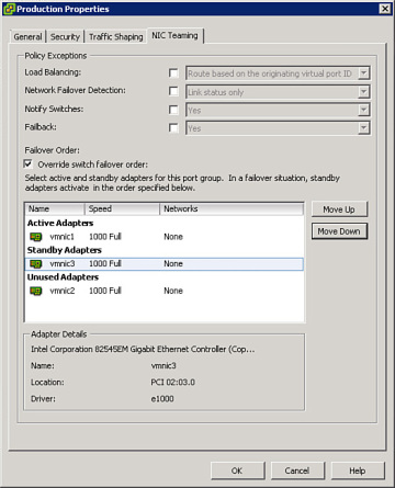
- Step 8. Repeat the previous steps to modify the Failover Order for Test, such that vmnic2 is Active, vmnic1 is Unused, and vmnic3 is Standby.
- Step 9. Click OK.
Scenario—NIC Teaming on a Distributed Port Group
Configure a port group named Production on a vDS named dvSwitch1 to use Uplink-3 to Uplink-6 with the Route based on physical NIC load teaming policy.
Set Failback to No.
On the same switch, configure the Management port group to use Uplink-1, but permit it to failover to Uplink-2 if necessary.
Ensure that each port group is configured to notify switches in the event of a failover.
This task can be accomplished by performing these steps:
- Step 1. Select Inventory > Networking.
- Step 2. Locate dvSwitch1 in the inventory view and expand its view.
- Step 3. Right-click the Production port group, and select Edit Settings.
- Step 4. Select Teaming and Failover.
- Step 5. Select the NIC Teaming tab.
- Step 6. Set the Load Balancing option to Route based on physical NIC load.
- Step 7. Set the Failback to No.
- Step 8. Check the box to Override the Failover Order.
- Step 9. By selecting each Uplink one at a time and using the Move Up and Move Down buttons, change the Failover Order such that Uplink-3, Uplink-4, Uplink-5, and Uplink-6 are Active. Likewise, set Uplink-1 and Uplink-2 as Unused.
- Step 10. Click OK.
- Step 11. Right-click the Management port group, and select Edit Settings.
- Step 12. Select Teaming and Failover.
- Step 13. Select the NIC Teaming tab.
- Step 14. Check the box to Override switch Failover Order.
- Step 15. By selecting each Uplink one at a time and using the Move Up and Move Down buttons, change the Failover Order such that Uplink-1 is Active. Likewise, set Uplink-2 as Standby and set Uplink-4, Uplink-5, and Uplink-6 as Unused.
- Step 16. Click OK.
[ufwp id=”1057142″]
Configure Port Groups to Properly Isolate Network Traffic
VCAP5-DCA configure using vSphere
VMware recommends that each type of network traffic in vSphere be separated by VLANs and be provided with the appropriate bandwidth.
To achieve this, the design typically allocates separate VLANs for management, vMotion, VMs, iSCSI, NAS, VMware HA Heartbeat, and VMware Fault Tolerance logging.
Typically, VMs are not placed on a single VLAN, but instead might use multiple VLANs.
The implementation requires that the VLANs be created within the physical network. Additionally, each virtual port group might require a specific configuration.
The most common and flexible means to provide virtual isolation between port groups is to configure each physical switch port with all virtually allocated VLANs configured in the virtual switch.
To do so, you “trunk” the VLANs on the physical switch using IEEE 802.1q trunking.
For example, if a physical switch port is trunked for VLANs 101–110, then 10 port groups should be created on the connected vSwitch, where each port group is assigned a unique VLAN number in the range from 101 to 110.
Administer vSphere Distributed Switches
This section is intended to ensure that you have the knowledge and skills to perform administration tasks on vDSes.
It covers command-line use, port binding settings, Live Port Moving, configuring vDS settings to satisfy specific network requirements, Network I/O Control, and troubleshooting.
Understand the Use of Command-line Tools to Configure Distributed Virtual Switch Settings on an ESXi Host
Although a vDS cannot be modified via vCLI commands because its control plane resides on a vCenter Server, vCLI commands can be used to control how specific ESXi hosts connect to the vDS.
Determine Use Cases and Apply Port Binding Settings
By default, a vDS port group contains 128 ports with static binding. You can change the number of ports.
You can also change the port binding method to dynamic or ephemeral.
Static binding means that existing ports are assigned to virtual adapters immediately when the virtual adapter is attached to the port group.
For example, if the port group contains 128 ports, then a maximum of 128 VMs can be connected to the port group regardless of the power state of the VMs.
Dynamic binding means that existing ports are not assigned to virtual adapters until the adapter becomes live.
For example, if the port group contains 128 ports, more than 128 VMs can be connected to the port group but no more than 128 of these VMs can actually be running at any given time.
As each VM powers on, their virtual adapter becomes live and is then assigned a port on the vDS within the port group.
As each VM is powered down or removed from the port group, that port becomes available for reassignment.
With ephemeral binding, ports are not pre-provisioned or assigned, but instead are created and assigned as virtual adapters become live and are connected to the port group.
During creation of a port group using the ephemeral port binding method, you do not need to specify a number of ports and no ports are immediately created.
As each VM is connected to the port group and started, a port is automatically created and assigned to the virtual adapter.
As each VM is stopped, its assigned port is unassigned and destroyed.
To change the binding method, right-click the port group and select Edit Settings. Change the binding type from static to either ephemeral or dynamic.
In a small environment, the standard approach could be to leave port groups with the default settings, which tend to be easy to configure and support.
In larger environments containing multiple port groups, it can be best to lower the number of ports in a port group in cases where you are certain that fewer than 128 virtual adapters will never connect.
This frees up otherwise unused ports for assignment to other port groups.
In cases where you expect to never have more than a specific number of concurrently running virtual adapters connected to a port group, you could set the port binding method to dynamic.
Ephemeral binding is the most flexible and scalable.
Ephemeral can be a good choice in most cases due to its flexibility and the fact that it allows additional VMs to be attached to the port group even when vCenter Server is offline.
Live Port Moving
Live Port Moving is a feature of vDSes that enables an active port to be migrated into a dvPortGroup without dropping the connection and while acquiring the settings of the target dvPortGroup.
This could be useful for troubleshooting. Enable Live Port Moving on a port group using the following steps:
- Step 1. Select Inventory > Networking.
- Step 2. Locate and right-click the appropriate port group; then select Edit Settings.
- Step 3. Select Advanced, and then select Allow Override of Port Policies.
- Step 4. Click Edit Override Settings.
- Step 5. Now, use the following PowerCLI commands to set the LivePortMovingAllowed property of the port group’s policy settings to true:
- $dvPg = Get-VirtualPortGroup -Name “Test” | get-view
- $var = New-Object VMware.Vim.DVPortgroupConfigSpec
- $var.Name = “Test”
- $var.ConfigVersion = $dvPg.Config.ConfigVersion
- $var.policy.LivePortMovingAllowed = “True”
- $var.policy.BlockOverrideAllowed = “True”
- $taskMoRef = $dvPg.ReconfigureDVPortgroup_Task($var)
Identify Distributed Virtual Switch Technologies to Satisfy Network Requirements
You should be able to analyze a set of network requirements and decide how to satisfy these requirements by implementing specific vDS features.
One way to gain this skill is to examine each available vDS setting and consider possible use cases.
Another means is to consider sample scenarios containing network requirements, decide which vDS features might be useful, and determine the best configuration of the feature to fit the requirements.
Here are a couple of sample scenarios:
Scenario—Manageability of Distributed Virtual Switches
Configure a vDS such that the administrator can still attach new VMs to the vDS even if vCenter Server is offline due to failure or maintenance.
This can be accomplished by configuring the port groups on the vDS for ephemeral binding.
which allows the administrator to connect VMs to the port group using the vSphere Client connected directly to the ESXi host.
Static binding and dynamic binding do not allow such changes without involving vCenter Server.
Scenario—Network Sniffing
On a vDS, configure a new port group named Sniffer that allows a VM running Wireshark to successfully inspect network I/O.
This involves two other VMs connected to two other port groups on the vDS whose VLANs are 101 and 102.
Do not allow the Wireshark VM to inspect any I/O from any other VMs, port groups, or VLANs.
This can be accomplished by adding a new port group named Sniffer to the vDS and making the following settings:
- Step 1. Select Inventory > Networking, and right-click the Sniffer port group.
- Step 2. Select Edit Settings.
- Step 3. Set the VLAN Type to VLAN Trunk.
- Step 4. Enter 101, 102 in the VLAN text box.
- Step 5. Click OK.
- Step 6. Select Inventory > VMs and Templates, and then locate the Wireshark VM.
- Step 7. Right-click the Wireshark VM, and select Edit Settings.
- Step 8. Select the network adapter, and change its connection to Sniffer port group.
- Step 9. Ensure that Connected and Connected at Power On are selected.
- Step 10. Click OK.
- Step 11. Select Inventory > Network, and select the vDS.
- Step 12. Select the Ports tab, and locate the source and Wireshark VMs.
- Step 13. For each of the source VMs, identify and record their port IDs. For example, the port IDs of the VMs could be ports 11 and 21.
- Step 14. Identify the port ID of the Wireshark VM. For example, the port ID could be 40.
- Step 15. In the inventory view, right-click the vDS.
- Step 16. Select the Port Mirroring tab, and then click Add.
- Step 17. Specify a name for the port mirroring session—for example, use Wireshark.
- Step 18. Select Allow normal I/O on destination ports.
- Step 19. Click Next.
- Step 20. Choose Ingress / Egress.
- Step 21. Type the port IDs of the source ports, separated by commas. For example, type 11, 21.
- Step 22. Click Next.
- Step 23. Click the >> link and enter the port ID of the Wireshark VM—for example, type 40.
- Step 24. Click Next.
- Step 25. Click Finish.
Configure and Administer vSphere Network I/O Control
VCAP5-DCA configure using vSphere
Network I/O Control is a feature of a vDS that provides the implementation of network resource pools.
Network resource pools, which are similar to DRS resource pools, are pools of network ports on which shares and limits can be set.
Network resource pools provide a means to control network I/O for specific data types that span multiple port groups.
Although port groups on vDSes provide Traffic Shaping policies that enable ingress and egress data to be limited per average bandwidth, peak bandwidth, and burst size settings.
Traffic Shaping alone cannot provide sufficient flexibility in certain situations.
You might want to control network I/O for a specific type of traffic that spans multiple port groups without having to manage settings on every port group.
You also might need to establish a priority level for certain types of traffic, so that critical network traffic is minimally impacted when network contention occurs.
For these use cases, Network I/O Control provides an effective solution.
[ufwp id=”3506256″]
To enable Network I/O Control, select the vDS, select the Resource Allocation tab, click Properties, and click Enable Network I/O Control on this vSphere Distributed Switch.
This turns on Network I/O Control and creates system network resource pools that correspond to the types of traffic recognized automatically by vSphere.
The system network resource pools are Virtual Machine Traffic, vMotion Traffic, Management.
Traffic, iSCSI Traffic, NFS Traffic, HA Heartbeat, Fault Tolerance Traffic, and vSphere Replication Traffic.
By default, the Host Limit on each pool is set to Unlimited and the Physical Adapter Shares on each pool is set to Normal.
The lone exception is the Virtual Machine Traffic pool whose Physical Adapter Shares is set to High.
This is done by default, so if network contention occurs, VM traffic automatically receives a larger portion of the network bandwidth than the other traffic types.
Enabling Network I/O Control provides the administrator with the means to easily control network bandwidth usage by traffic type.
For example, consider a case where a cluster of ESXi hosts uses two 10 Gbps NICs and no other network adapters.
When vacating all VMs from a host to prepare for maintenance mode, eight concurrent vMotion operations can execute, which expedites the process.
However, the administrators might be concerned that if multiple concurrent vMotion operations occur during periods of heavy network activity.
Network contention could occur and negatively impact the performance of production applications.
The goal is to allow vMotion to heavily utilize bandwidth when it is available but to limit the bandwidth usage of vMotion if contention occurs.
This can be accomplished by enabling Network I/O Control and setting the Physical Adapter shares on vMotion Traffic to Low.
Network I/O Control also enables the creation of user-defined network resource pools that are containers of vDS port groups.
To create this type of pool, click the New Network Resource Pool link on the Resource Allocation tab.
To assign a vDS port group to the pool,
click the Manage Port Groups link on the Resource Allocation tab and use the drop-down menu for each port group,
to assign each port group to the appropriate network resource pool.
Scenario—User-defined Network Resource Pools
Configure a Network I/O Control to provide High shares for all production VMs and Low shares for all test VMs.
Twenty port groups are used for production VMs and named from Prod101 to Prod120.
The VLAN ID of each is uniquely assigned from 101 to 120. Twenty port groups are used for test VMs and named from Test201 to Test220.
The VLAN ID of each is uniquely assigned from 201 to 220.
This task can be accomplished by performing the following steps:
- Step 1. Select Inventory > Networking, and then select the vDS.
- Step 2. Select the Resource Allocation tab.
- Step 3. Enable Network IO Control.
- Step 4. Click New Network Resource Pool, and then name it Production.
- Step 5. Set the Shares to High.
- Step 6. Click OK.
- Step 7. Click New Network Resource Pool, and then name it Test.
- Step 8. Set the Shares to Low.
- Step 9. Click OK.
- Step 10. On the Resource Allocation tab, click Manage Port Groups.
- Step 11. For each port group named Prod101 to Prod120, select the Production resource pool in the drop-down menu.
- Step 12. For each port group named Test201 to Test220, select the Test resource pool in the drop-down menu.
- Step 13. Click OK.
Summary
This chapter described how to perform network administration in vSphere environments.
It provided details on administration procedures involving the use of the vSphere Client, the vCLI, and PowerCLI.
At this point, you should ensure that you can successfully apply the material in this chapter.
to perform network administration tasks in an actual vSphere environment.
Exam Preparation Tasks- VCAP5-DCA configure using vSphere
[ufwp id=”3506256″]
Review All the Key Topics
Table 2-2 provides a discussion of the key topics.
Use this table as a quick reference to sample administrative tasks that you should be capable of performing in preparation for the exam.
For each task, ensure that you can accomplish the task using the vSphere Client, the vCLI, and PowerCLI, where appropriate.
Table 2-2 Key Topics for Chapter 2
| Key Topic Element | Description | Page |
| List | Procedure for configuring SNMP receivers on a vCenter Server | 59 |
| List | Commands to configure SNMP on an ESXi host | 61 |
| List | Procedure for configuring VMware Direct Path I/O | 62 |
| List | Migrating VMs, vmkernel ports, and NICs while attaching an ESXi host to a vDS | 63 |
| Paragraph | esxcli network vswitch namespace | 66 |
| List | Procedure for configuring NetFlow | 68 |
| List | Procedure for configuring LLDP | 69 |
| List | Commands to configure VLAN on standard port group | 70 |
| Paragraph | Use cases for private VLANs | 72 |
| List | Procedure for configuring PVLANs | 73 |
| Paragraph | Description of Load-Based Teaming | 75 |
| List | Procedure for configuring Live Port Moving | 81 |
| Paragraph | Procedure for enabling Network I/O Control | 83 |
Definitions of Key Terms
Define the following key terms from this chapter, and check your answers in the glossary.
- Standard vSwitch (vSS), Distributed vSwitch (vDS), MTU, Jumbo Frames, SNMP, Traffic Shaping, NIC Teaming, Etherchannel, VLAN, VLAN Trunking, Direct Path I/O, Network I/O Control, network resource pool, Promiscuous Mode.
Review Tasks VCAP5-DCA configure using vSphere
These Review Tasks allow you to assess how well you grasped the materials in this chapter.
Because of the advanced and hands-on nature of this particular exam, a set of tasks is provided instead of a set of questions.
You should now attempt to perform each of these tasks without looking at previous sections in this chapter or at other materials, unless necessary.
The steps for each task are located within the chapter.
- Configure SNMP on vCenter Server and on each ESXi host.
- Configure Direct Path I/O for one or more network adapters.
- Build a vDS and host migrate all VMs, vmkernel ports, and network adapters from an existing vSS.
- Create a vSS, add a virtual switch port group, attach uplink adapters, and assign VLANs using the esxcli namespace.
- Configure a vSS to support LLDP and Jumbo Frames.
- Configure PVLANs on a vDS, including at least one isolated PVLAN, one community PVLAN, and one promiscuous PVLAN.
- Configure Network I/O Control and create a user-defined network resource pool that maps to at least two vSwitch port groups.
This class is taken from the book “VCAP5-DCA Official Cert Guide: VMware Certified Advanced Professional 5- Data Center Administration
[ufwp id=”3506256″]
VCAP5-DCA configure using vSphere